 자동차
자동차
 트럭
트럭
 버스
버스
 모터사이클
모터사이클
 군용 차량
군용 차량
 전자 기기
전자 기기
 무기
무기
 건축물
건축물
 항공기
항공기
 가구
가구
 캐릭터
캐릭터
 동물
동물
 우주선
우주선
 음식
음식
 선박
선박
보기
Maybe you’re a game developer with great ideas but no models, an artist hoping to break into the gaming industry, or an aspiring modder; whatever the reason, you’ve decided you need to learn how to make game assets. But the further you look into 3D modeling, the more complicated it seems to get… was this a bad decision?
Maybe! But before you decide to quit, keep reading – because in this article, I’m going to go over everything you need to create this cute, low-poly game asset; and I’ll introduce all the essential tools for modeling, so that you can go on to create anything you can imagine!
Before we go into the tutorial itself, let’s take a step back and talk a little bit about game assets and art in general.
To start with: What makes something a “game model” in the first place? And what makes game art different from 3D assets for films, renders, etc.?
Well, the main thing that makes game assets unique is that video games generally have fairly strict graphics limitations. Unlike movies, for which individual frames of animation can take days to render, video games are rendered in real-time – the computer has to make all the rendering calculations almost instantaneously, which means that models and textures for games usually need to be limited in terms of complexity and file size. This means that assets need to be created in such a way that they both don’t have too many faces (or polygons) to be rendered, and also don’t have textures that take up large amounts of memory.
These limits depend on the intended platform for the game – mobile, console, PC, and virtual reality all have different requirements; and when creating a game design, you have to take these limits into account!
There are many ways to get around these issues – in game development, physical details are often “faked” using special textures called Normal Maps to save on polygon count, and textures are repeated throughout models using Tiling and Trimsheets to avoid using too much memory.
But since today’s project is aimed at beginners, I’ll be taking a simpler approach – we’ll be modeling in the Low Poly style, common in many games and loved for its cute, minimalist aesthetic. By their very nature, low poly style assets are perfectly suited for games – they have the words “low poly” right there in the name, and as you’ll see, textures are usually very simple as well!
Overview
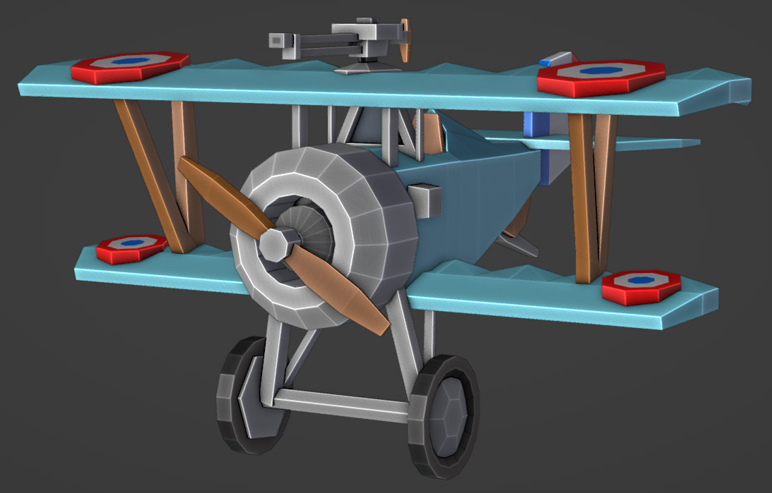
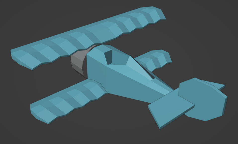
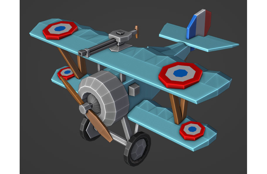
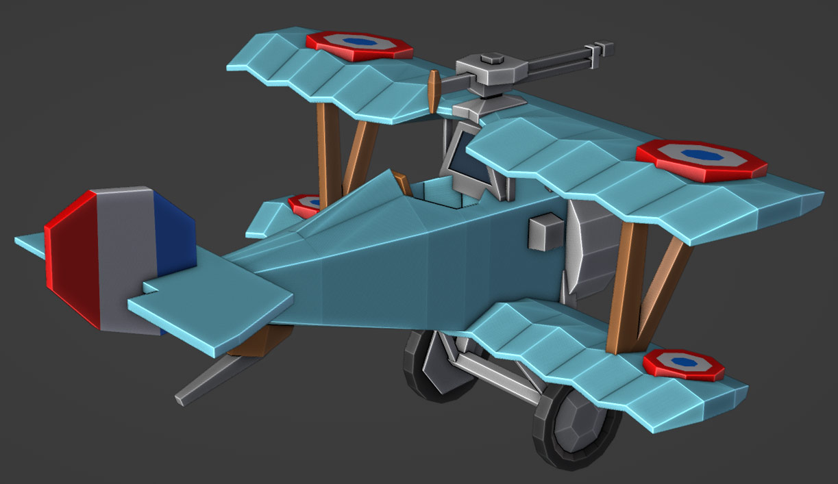
For this project, I’ll be showing you how to create a low-poly, game-ready version of the Nieuport 17 biplane created by the French in World War 1 – but feel free to make the project your own as you go through the tutorial!
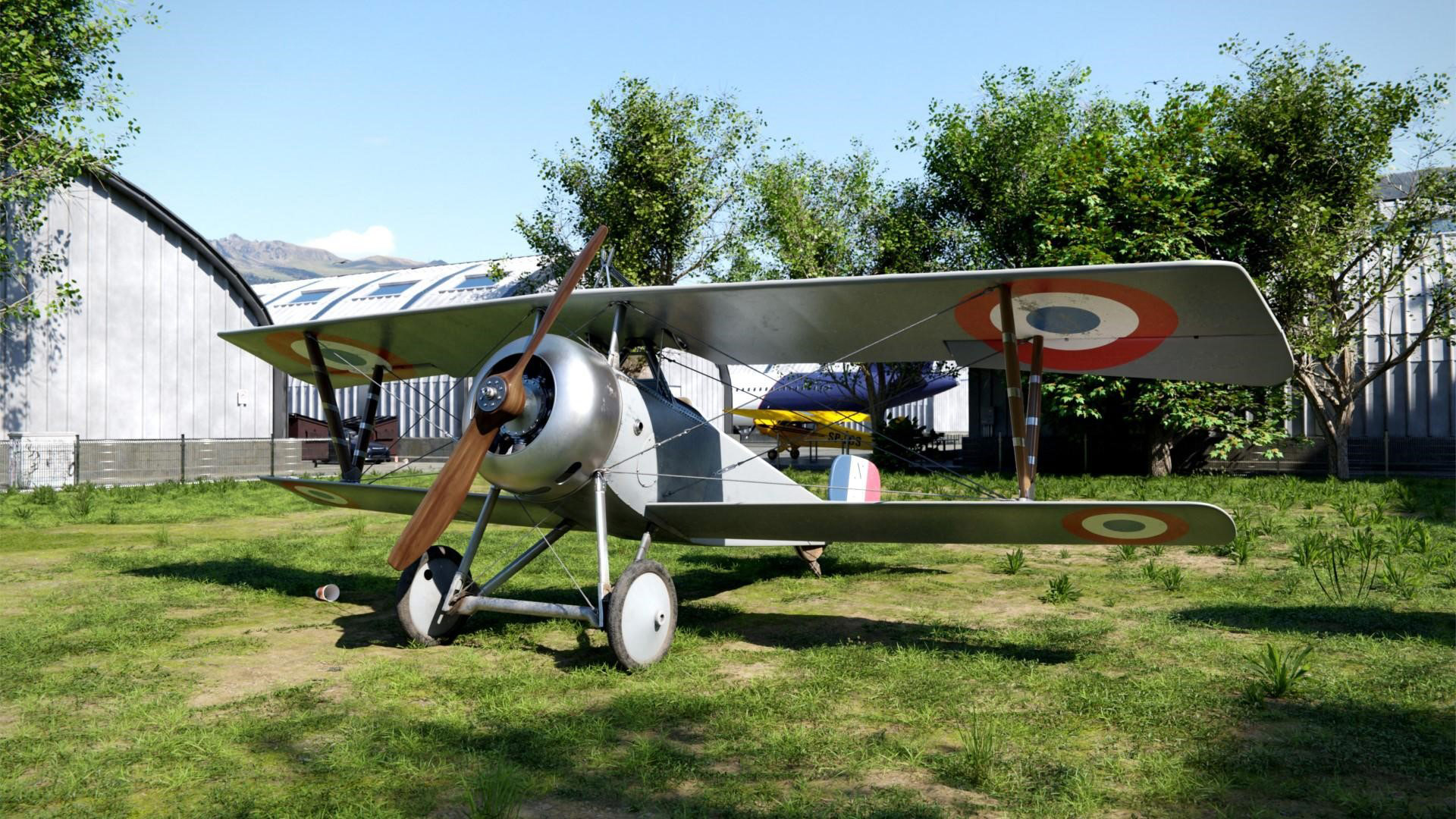
I chose this plane in particular because I created a more realistic model of it as a personal project (as seen above) – but ultimately, 90% of the tools I used for that project were exactly the same ones I’ll be introducing in this tutorial!

For this tutorial, we’re going to use the free, open source Blender 3D software from blender.org. This is a fantastic program, especially for modeling, rendering, and animation – Blender is a powerful tool for pro game artists, but because of the vast amount of free tutorials online, it’s also a perfect entry into 3D for beginners!
Before we get started on the steps of the tutorial, let’s go over some Blender basics to get you comfortable in the software!
After downloading Blender from Blender.org, this is more or less what you should see when you open it up:
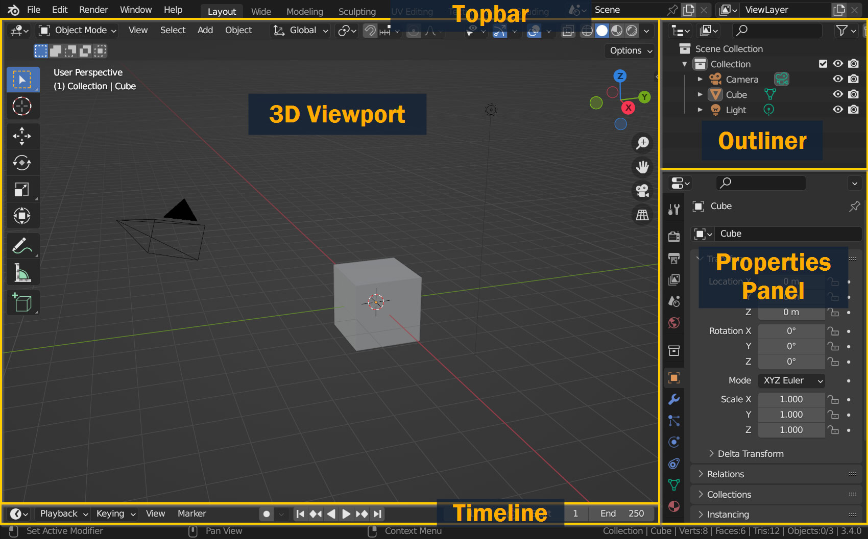
This is the default layout of Blender, and this is what you’ll be working with most of the time while 3D modeling!
The Blender interface is separated into several Areas, which are used for different tasks in 3D. You can move areas around by clicking and dragging on the borders between them, and merge and create new areas by dragging outward and inward from the corners – and you can change which Editor is contained within each by selecting one from the dropdown in the top-left corner of every area.
But for this tutorial, we won’t need to change these – for most tasks, Blender’s preset Workspaces listed in the Topbar will suffice!
Each workspace is different, but for now I’ll just go over the default Layout interface, which is where you’ll likely be working most often:
Later in the tutorial we’ll be visiting the Shading and UV Editing workspaces as well – but I’ll talk about those when we get to those steps!
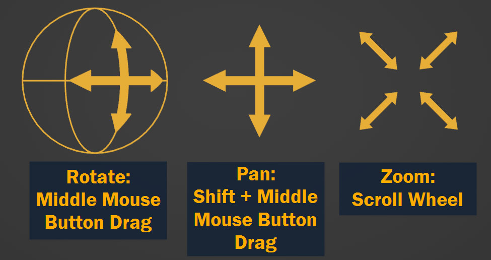
In addition to understanding the basic interface, one of the most important things to know in Blender is how to move the viewport and interact with your 3D scene!
With Blender open, try these out and see if you can get a feel for them:
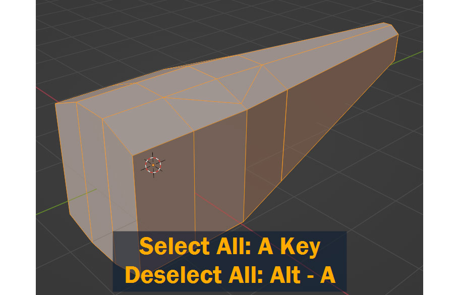
In addition to moving the camera, you can Select objects by clicking on them – pressing A and Alt/Option – A will select and deselect everything in the scene, and pressing H and Alt/Option – H will hide and unhide objects respectively. Try these out with the default objects in the 3D scene!
Additionally, the G, R, and S keys Move, Rotate, and Scale objects – simply press the key, move the mouse to do the action on the object, and left click or press enter to confirm!
Like most other programs, use Ctrl/Cmd – Z to Undo actions, Ctrl/Cmd – Shift – Z to Redo, and be sure to press Ctrl – S often to save your file and avoid losing work!
I’ll leave it at that for now – practice those basic actions on the default objects in the scene, and when you’re ready to move on, continue to the next section!
Finally, we’re actually starting on the project itself!
To start out, let’s focus on building the basic shape for the Body of the airplane.
For this project, let’s start out by using the Default Cube. Select the cube by left clicking it, and press the Tab key to enter into edit mode – this will allow you to edit the individual Vertices, Edges, and Faces on the object!
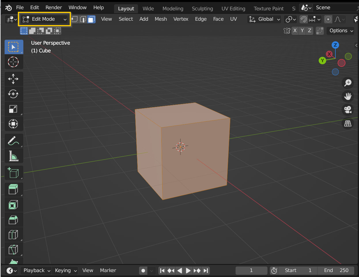
When you’re in Edit Mode, you can choose between selecting Vertices, Edges, or Faces on your model – at the top of the 3D viewport you’ll see an indicator that shows you which one you’re currently selecting, and you can press the 1, 2, or 3 keys on your keyboard to quickly switch between Vertex, Edge, and Face selection modes. For now, press 3 to enter into Face Select mode.

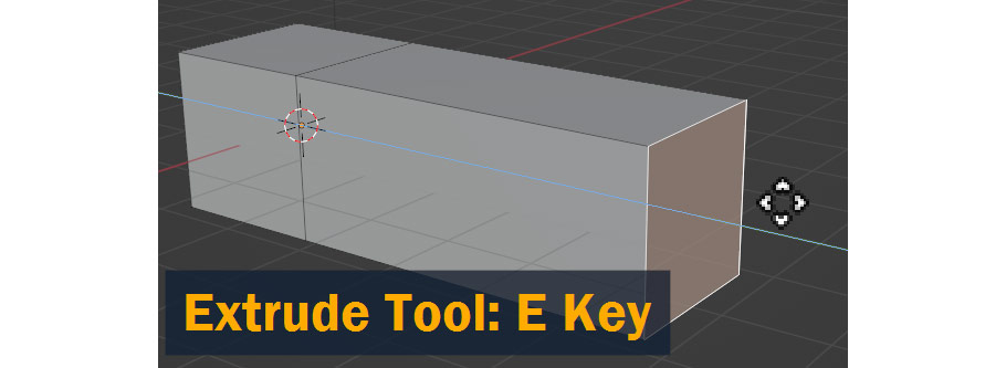
Now, let’s get modeling! To start with, let’s extend the back of the cube object to create the basic shape for the airplane body. First, Select the face on the cube by Left Clicking – next, press E to Extrude the face outward as shown! When you have it at the correct length, Left Click to confirm.
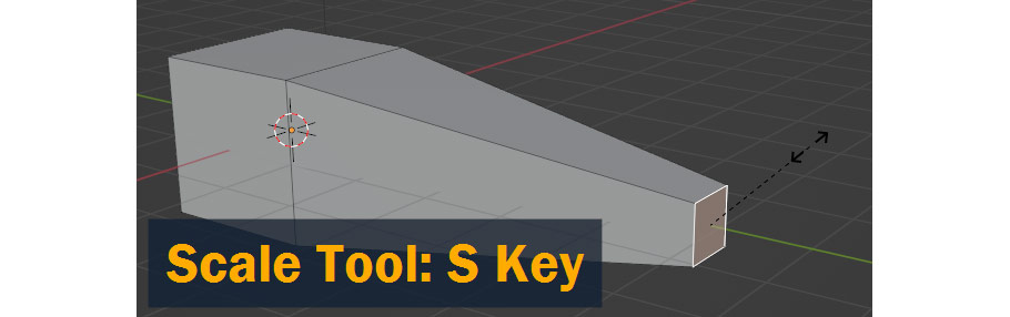
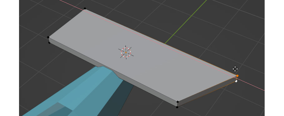
Now, let’s Scale the new extruded face inwards to create a taper towards the back of the airplane. With the rearmost face selected still, press S and move your mouse to Scale the face inward. Once again, when it’s the right size Left Click to confirm the action – if you don’t like the result, remember you can always press Ctrl/Cmd – Z to undo!
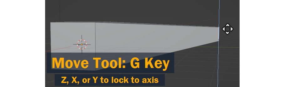
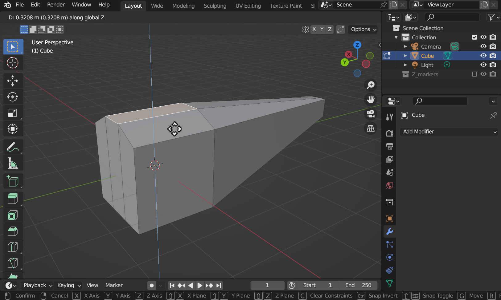
Next, with the same face selected, let’s Move it upwards by pressing G – and since we only want to move the face upwards, we can lock the movement to the Z Axis by pressing the Z key. Again, Left Click when you’re done!
With the rough shape out of the way, let’s get some more details on your model!
To start with, let’s add some more edges going lengthwise – right now, we don’t have very much geometry to work with.
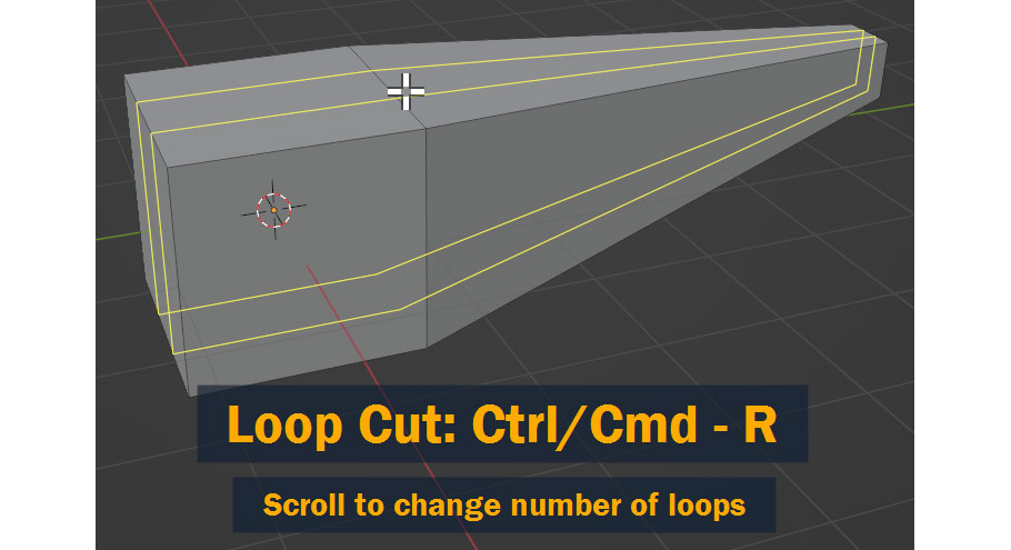
To add edges, use the Loop Cut tool by pressing Ctrl/Cmd – R on your keyboard, and hovering over an edge to add your loop to that area – at this point, you can also use the Scroll Wheel to change the number of edges being added to two. When the correct number of edges are being shown in the right place, Left Click to confirm!
After left clicking, you’ll be given the ability to Slide the new edges – but we don’t need this right now, so Right Click to cancel this action.
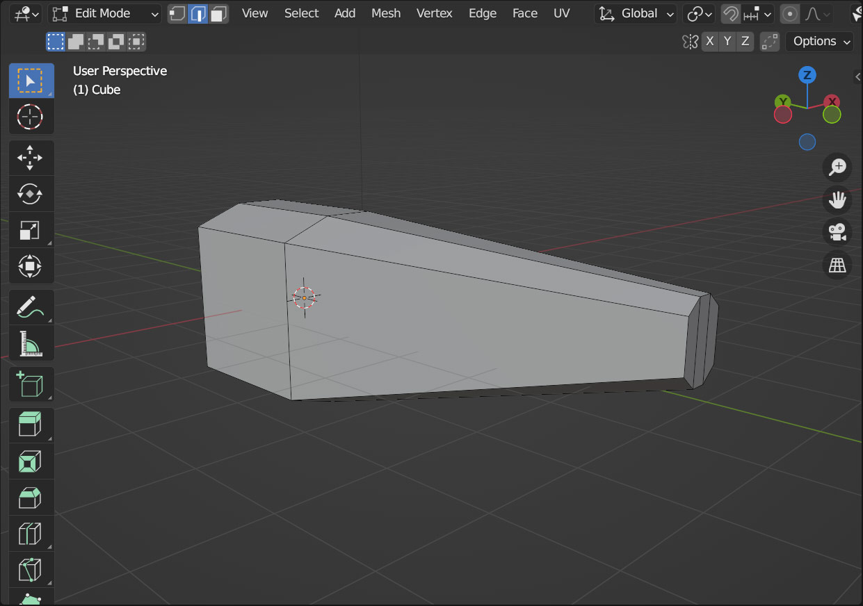
With the new edges in place, we can now form the rounded shape of the airplane body. Like before, Select the center face at the front of the model and press G and Z to move it upward along the Z Axis – and again, Left Click to confirm!
Repeat this with other parts of your model to give it a rounded shape – and remember that you can use 1, 2, or 3 on your keyboard to switch between Vertex, Edge, and Face selection!
Now, let’s create a simple cockpit for the airplane.
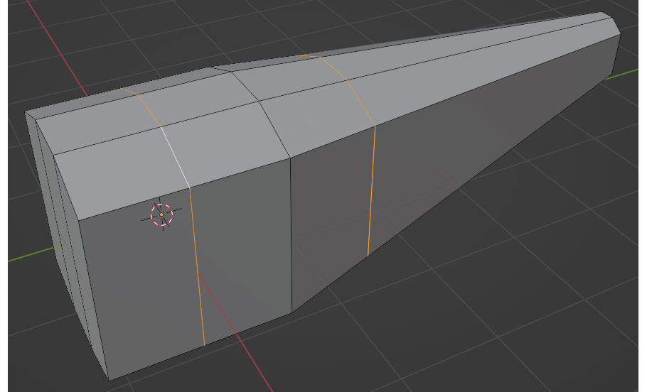
To start with, we’ll need to once again add some more geometry with Ctrl/Cmd – R to add two more Loop Cuts to support the cockpit modeling. This time, instead of canceling the sliding operation after adding the cuts, see if you can match what I’ve done here:
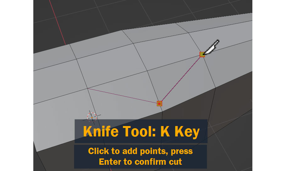
With those new edges added, we can now cut out the shape of the cockpit using the Knife tool. To access this, press K on your keyboard and click on your model to add a cut – to change direction, click again, and when you want to confirm press Enter!
I’m only doing the cut on one side of the model, because in the next step we’re going to mirror the geometry to the other side.
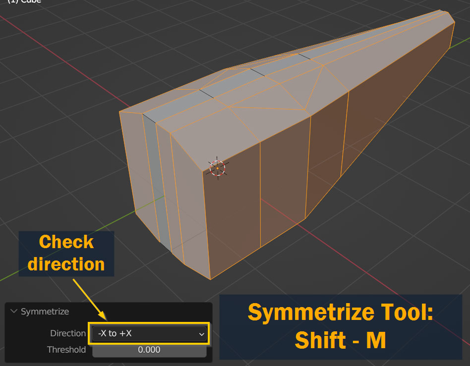
Now let’s mirror our model! First, select everything using the A key.
Now, to mirror or Symmetrize the selected geometry, press Shift – M. Depending on how you modeled your airplane, it might look wrong at first – if this is the case, you might need to change the Direction setting in the pop-up at the bottom of the screen after using the Symmetrize tool.
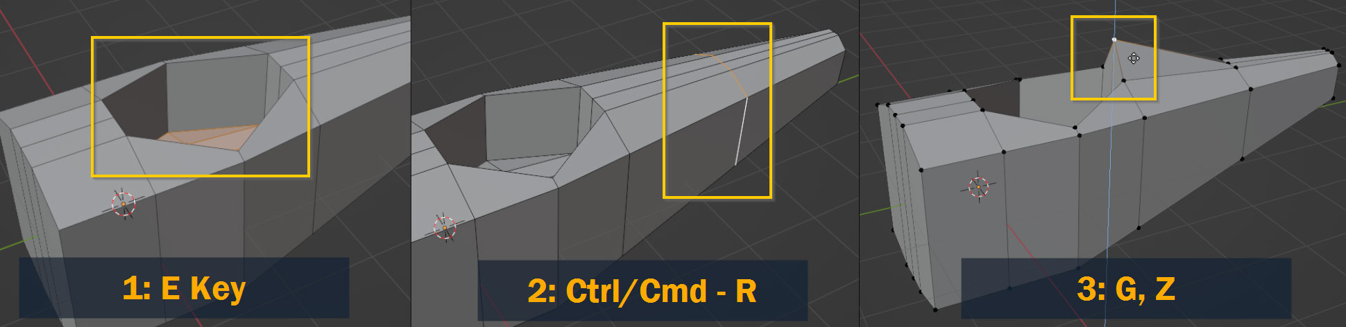
Next, I created the cockpit shape by first extruding the cockpit shape inwards by selecting it and pressing E, adding a loop cut to the rear section using Ctrl/Cmd – R, and lifting up the vertices behind the cockpit using G and Z to lock it along the Z axis.
Again, remember to use the 1, 2, and 3 keys to switch selection modes!
Before we move on to the next step, let’s go back into Object Mode by pressing Tab.
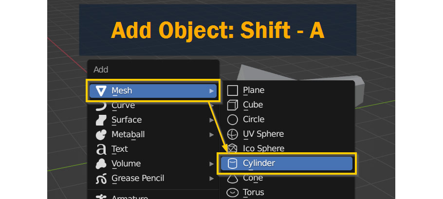
To finish up the body section, let’s create a cylinder object to act as the engine cover for our airplane!
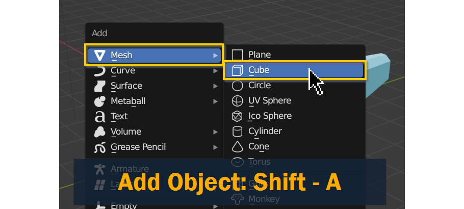
To start out, first press Shift – A to add a new object – from the Add menu that appears, select Mesh > Cylinder.
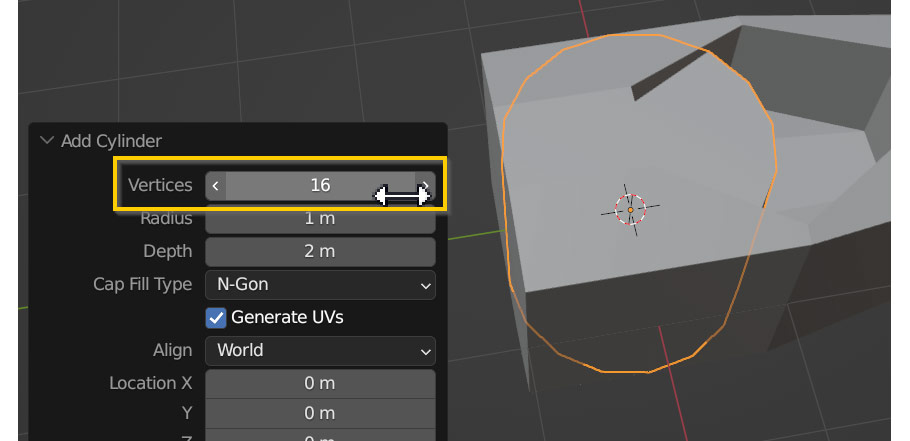
Before anything else, let’s edit the cylinder object a little bit – after you add the cylinder object, navigate to the Add Cylinder pop up at the bottom of your screen and open it!
Since this is a “Low Poly” style model, let’s decrease the Vertices value to something lower, simplifying the cylinder shape. I chose 16, but the exact value isn’t important!
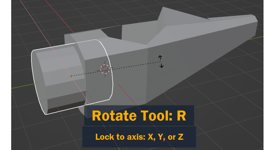
Once the cylinder is adjusted, we’ll need to Rotate it along the X axis by 90° to align with the body of the plane. To do this, press R to rotate, then press X to rotate along the X axis, type “90”, and press enter!
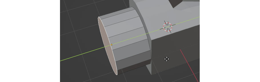
At this stage, we can also use G and Y to move the cylinder forward along the Y axis to align with the front of our body object.
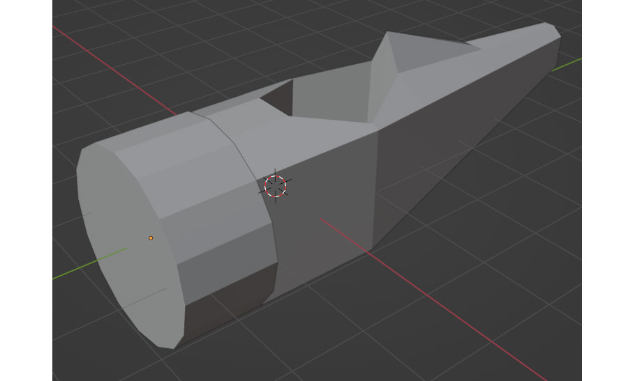
Next, let’s enter into Edit Mode by pressing Tab, and selecting the front face of the cylinder, use G and Y to move it along the Y axis and make it a bit shorter.
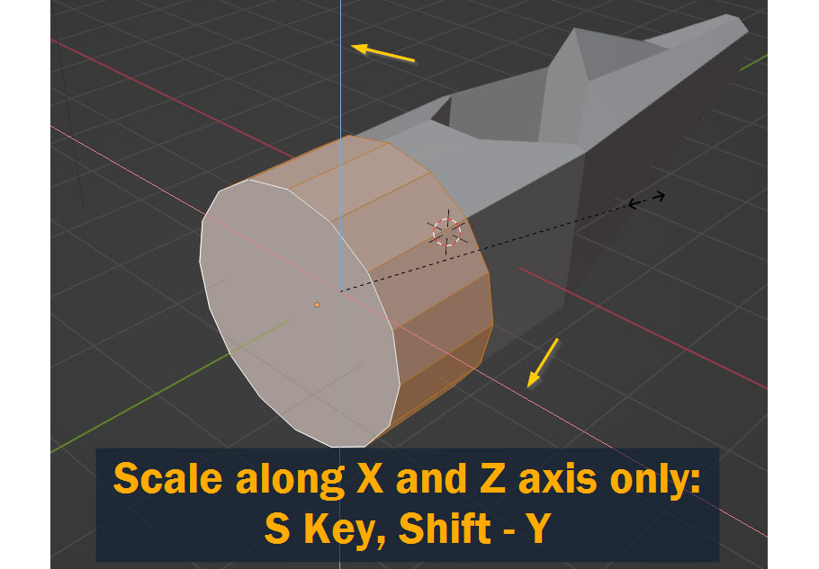
We should also probably make the cylinder wider to match the body of the airplane. To do this, select all using A and press S to scale, and then Shift – Y to prevent scaling along the Y axis.
As we’ve seen, pressing X, Y, or Z while rotating, scaling, or moving locks the movement to those axes, but adding Shift at the same time does the opposite, preventing movement along only that axis!
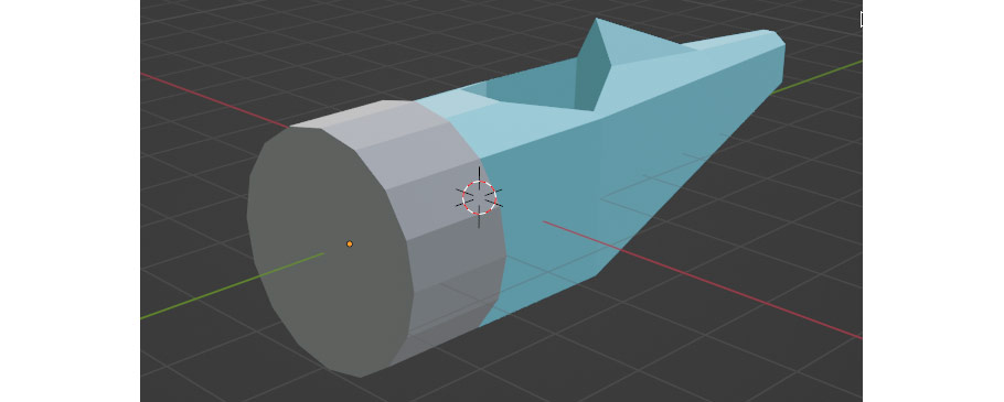
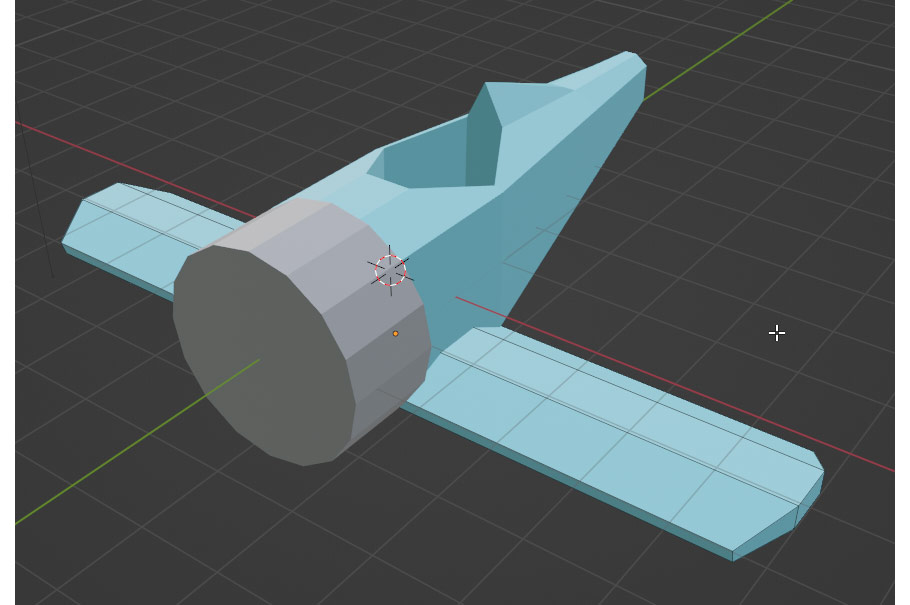
After entering back into Object Mode, this is what we’ve got so far! You can already see the basic shape of the airplane taking shape.
With the body done, let’s take a quick break from modeling!
In this section, I’ll go over a method for creating and applying a simple set of colors to your model that will translate well when you export it to a game engine.
Where texturing work is concerned, this is a very basic setup – but for low-poly style work like this, it can be very effective!
Before we begin, be sure to download the texture from here.
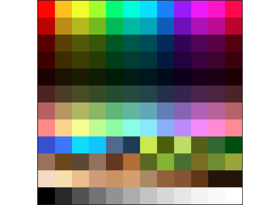
This texture is a grid of various colors that I created for this purpose – it’s only 12 * 12 pixels, but for projects like this, that’s all we really need!
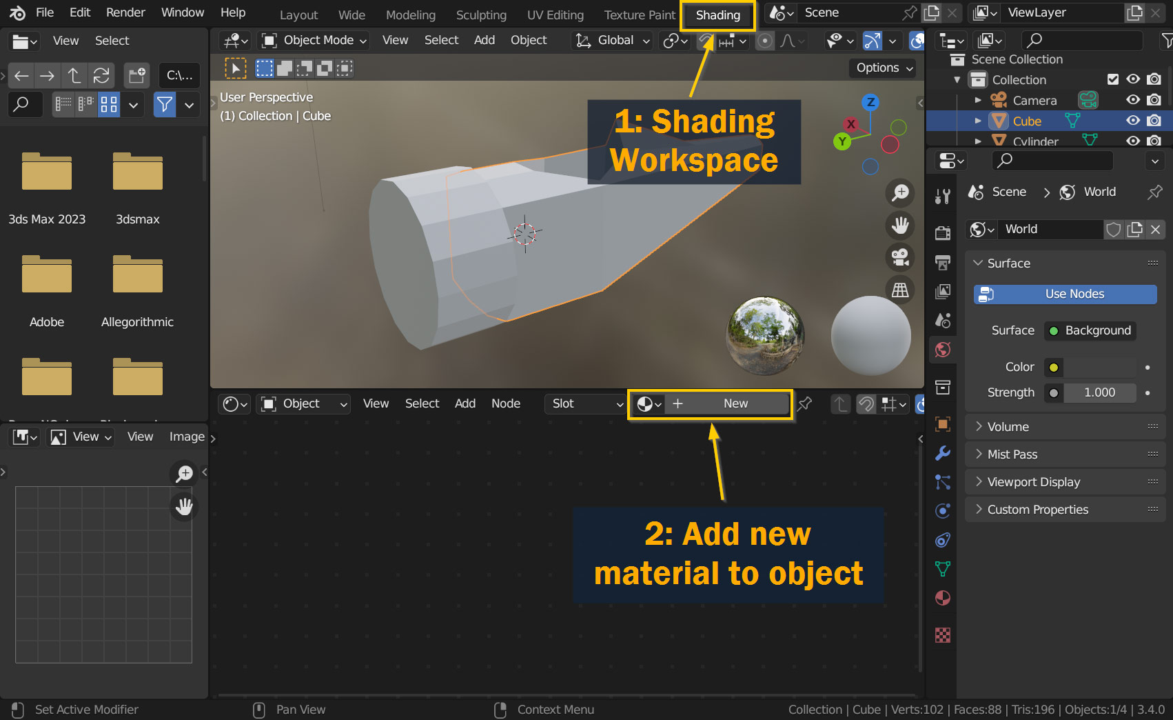
To start with, we need to navigate to the Shading workspace and create a new material on our object.
To switch to the Shading workspace, navigate to the Topbar and click the tab that says Shading – Blender will switch the interface setup to match the screenshot shown below!
The shading workspace contains a few new editor types: on the left are a File Browser and an Image Editor, in the center is the familiar 3D Viewport and the Shader Editor, and the Outliner and Properties Panel are left unchanged on the right side. For this tutorial, we’ll only really be using the 3D Viewport and the Shader Editor.
In the Shader Editor, let’s create a new material for our object; press the button labeled New to create a new material! Once it’s created, feel free to give it a name in the text box that replaces the New button.
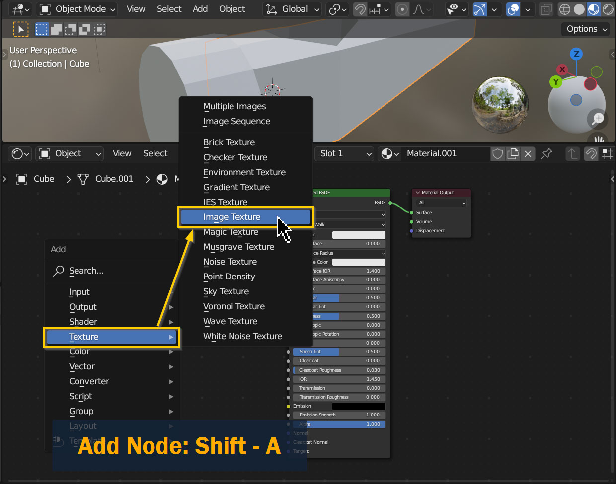
With your new material created, now we need to add an Image Texture node to put our color palette texture in!
Just like when adding a new object in the 3D view, to add a new node press Shift – A, go to Texture and select Image Texture.
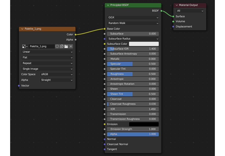
Connect the new Image Texture node to the Base Color input on the Principled BSDF node by dragging between the Color output and the Base Color input on the Principled BSDF. Now, anything that’s loaded into the Image Texture node will be displayed on your material!
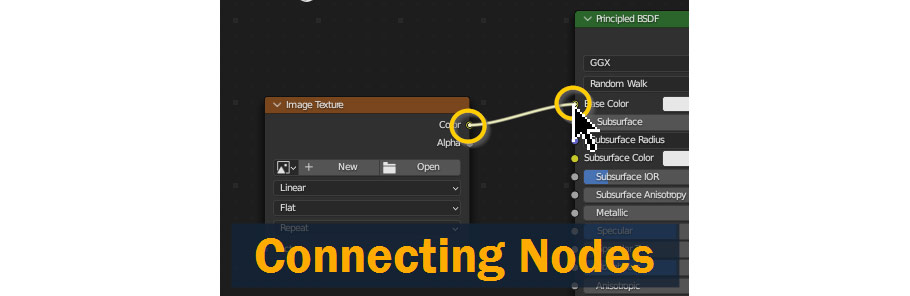
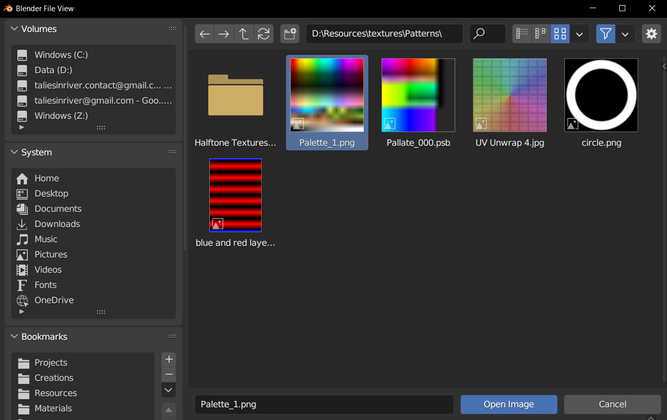
With the nodes connected as shown, now press the Open button on the Image Texture node, and navigate to the color palette texture wherever you saved it on your computer – select it and press Open Image.
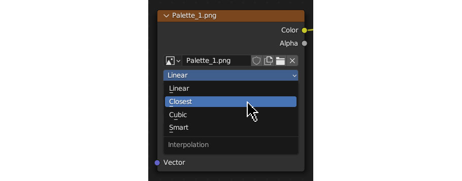
If you look at the texture on your model right now, you might notice that it appears blurred because of the low resolution texture. To get rid of this blurring, click on the image texture node where it says Linear and select Closest instead – this will display the pixels as individual squares instead of trying to smooth them out!
With that, the material setup is now complete! Now, we can start assigning colors to our model.
Let’s start assigning colors!
For this section, we’re going to be using the UV Editing workspace; so just like before, go to the Topbar and select UV Editing.
You’re also probably going to want to see the colors on your model for these steps – to do this, press the Z key in the 3D viewport and select Material Preview.
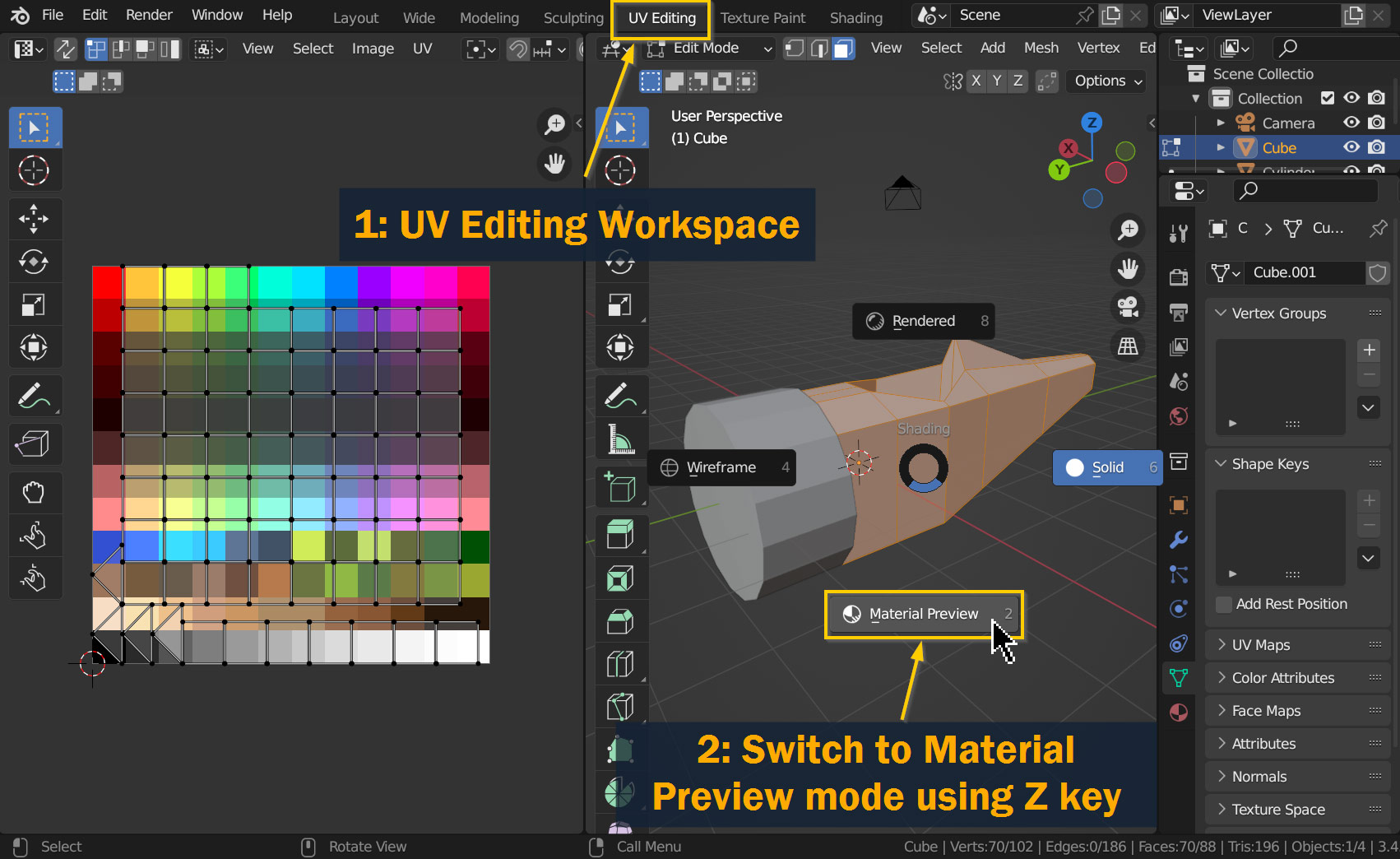
So, what are we looking at here? Well, on the left we have the UV Editor, which is, as you might have guessed, for editing and creating UV Maps. UV Maps are an essential part of the texturing process in 3D – a UV map is essentially a flattened version of your model, laid out in a 2D space. Think of it like a paper model; if the 3D object is the assembled model, the UV map is the unfolded version.
In 3D art, UV maps are how you control where textures are placed on your model. Try selecting and moving the faces in the UV map using G; you’ll notice as you move the faces on the UV map, different parts of the texture show up on your model!
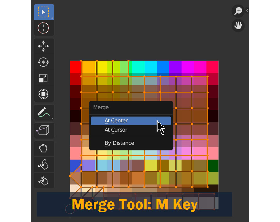
UV maps can get complicated, but for this project we’re going to skip most of that – since the parts of the model only need to be single, solid colors, we can simply collapse all the faces on the UV map into a single point and move it to the color we want for those faces!
To do this, Select the faces on your model that you want to choose a color for. Those faces will appear in the UV editor, where you can select them again (try A to select all). Next, press M and select At Center to merge the selected faces into a point.
Finally, move the selection (now a single point) to the color of your choice! For the body of the airplane I chose a light blue color, even though the real-life body is gray – I thought the blue would look a bit more soft and playful, which is generally the feeling I’m going for with this model!

Back in the Layout workspace, you can assign the new material you created to the Engine Cover as well – to do this, go to the Properties Panel, and open the Material Properties tab (as shown below). Here, you can open the dropdown next to the New button and select the material you created earlier!
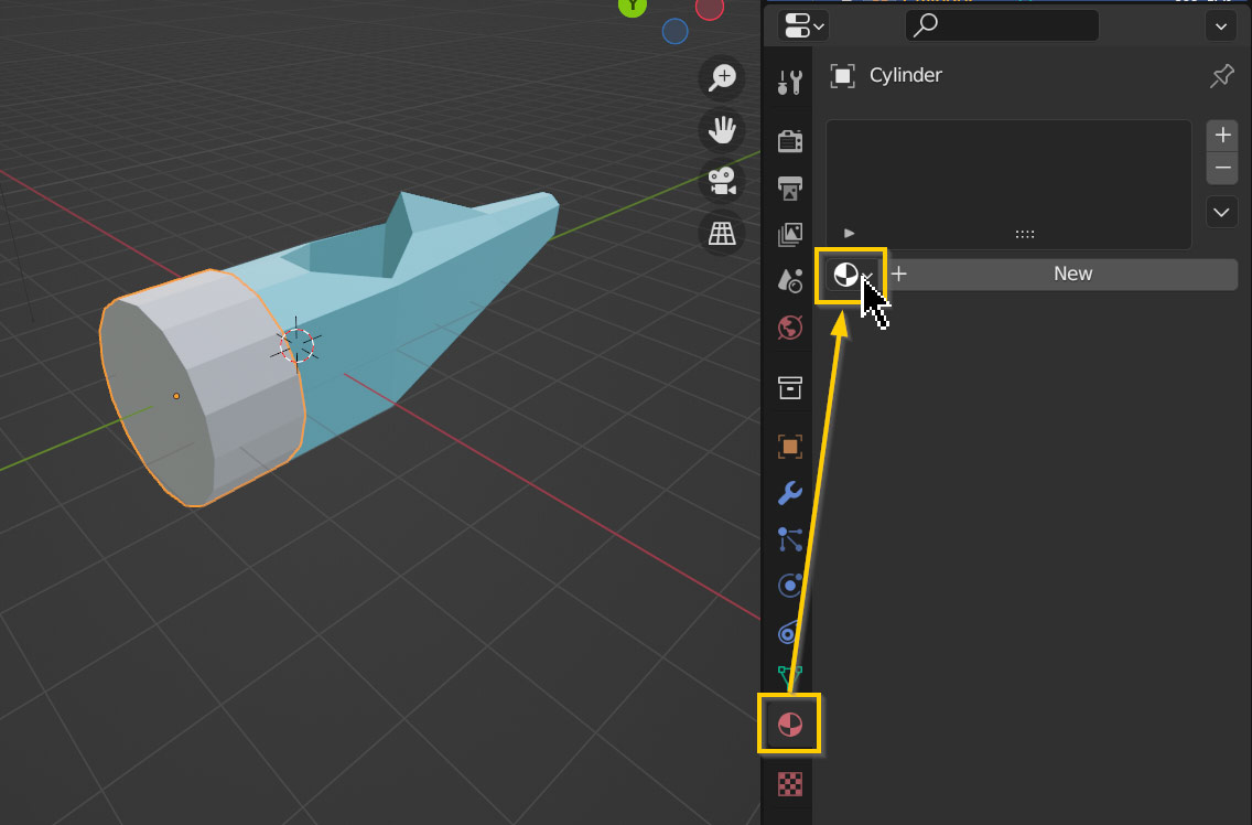

With the material assigned to the engine cover, go back to the UV Editor workspace and repeat the same steps as before to select a color; I went with this light gray to represent the bare metal on the real-life plane!
Let’s get back to modeling! For this part, I’ll be working on the wings and tail of the biplane.
To start with the wings, I first added a Cube object to the scene with Shift – A.
After pressing Tab to enter into edit mode, I then Scaled the cube to better represent the shape of a wing – first I scaled it down vertically with S and Z (to lock the action to the Z Axis), then I scaled it lengthwise using S and X.
Back in Object Mode, I also positioned it using G to move it and Shift – X to lock the movement onto the Y and Z axes.
To make it more wing-shaped, I added two Loop Cuts along the length of the wing using Ctrl/Cmd – R, and moved the edges on the wing using G and Shift – X to form the shape as shown.
I also repeated the steps from the UV Mapping section to assign the same light blue material to the wing!
Let’s flesh out some of the details on our wing! Since this is low-poly style, we don’t need much – but even for simple styles like this, some details are very important.
First of all, I moved the middle face on the end of the wings outwards as shown below using G and X – I then mirrored the edit to the other side using Shift – M as before!
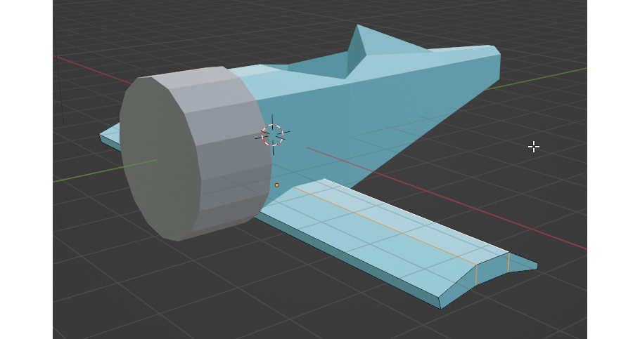
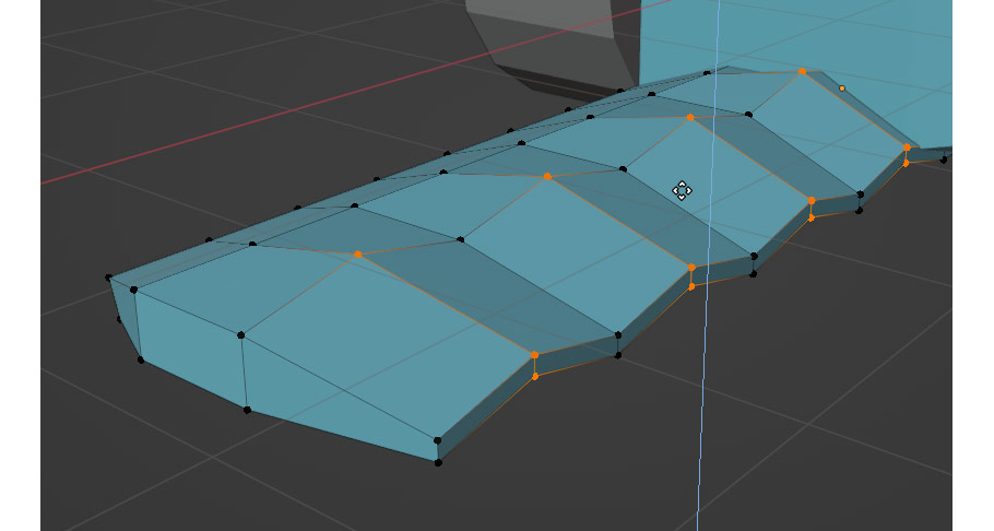
I wanted to add some repeating shapes to the wing to break up the monotonous straight edges. I started by using Ctrl/Cmd – R to add a few edge loops along the length of the wing – to add multiple loops at once, use the Scroll Wheel to increase the amount of cuts!
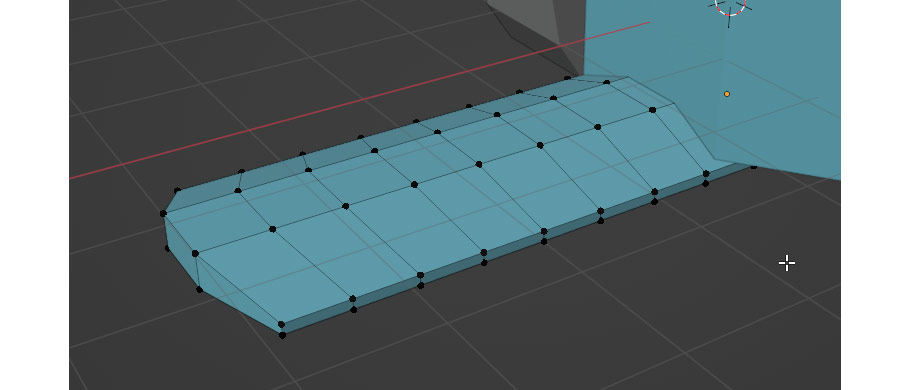
I then selected the vertices on the rear of the wing as shown, and moved them upward using G and Z as shown to add some visual interest to the wing. Be sure to switch to Vertex Select mode first by pressing 1 on your keyboard.
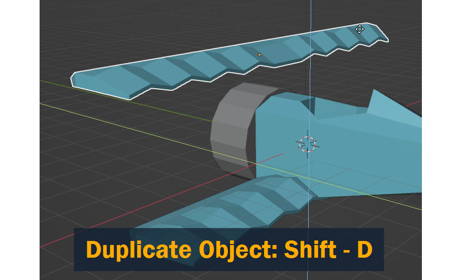
Back in Object Mode, I then Duplicated the wing object using Shift – D, and then pressing Shift – X to lock the movement along the Z and Y axes, in order to move the wing upward and forward.
I also adjusted the shape of the wing by going into Edit Mode and using the S key to Scale it, making it longer and wider to match the real-life airplane.
Now let’s focus on the tail area!
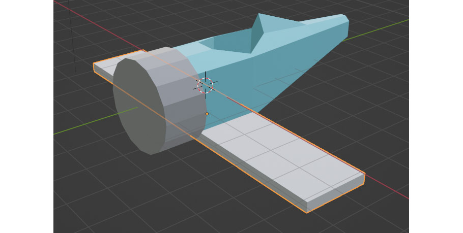
For this part, I want to introduce the 3D Cursor. This is a great tool that allows us to do many things in 3D – and importantly for this step, all new objects we add to the scene appear at the location of the 3D cursor!
So, since we’re about to create the rudder and vertical stabilizer on the tail area of the airplane, let’s move the 3D Cursor over there.
To do this, Select the airplane body, press Tab to enter into Edit Mode, and select the center-top vertex at the end of the tail.
Now, press Shift – S on your keyboard and select Cursor to Selected in the pie menu that pops up. You’ll notice once you do this, the lifering-like 3D cursor will move to the location of the selected vertex!
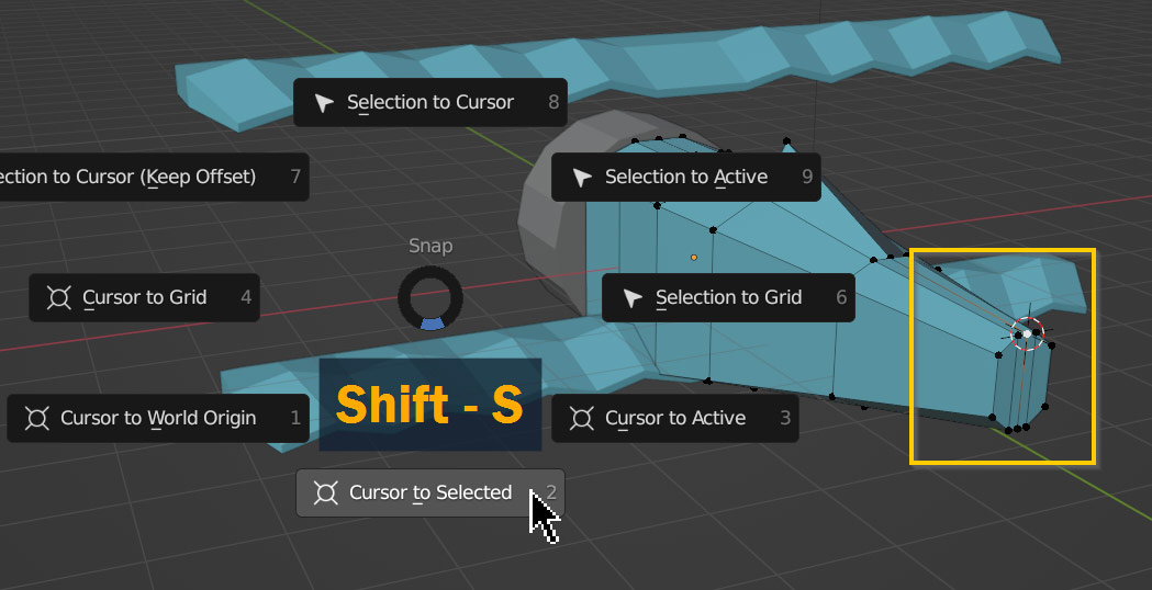
Now, when you add a cube using Shift – A, it will appear at the end of the tail, right where we need it.
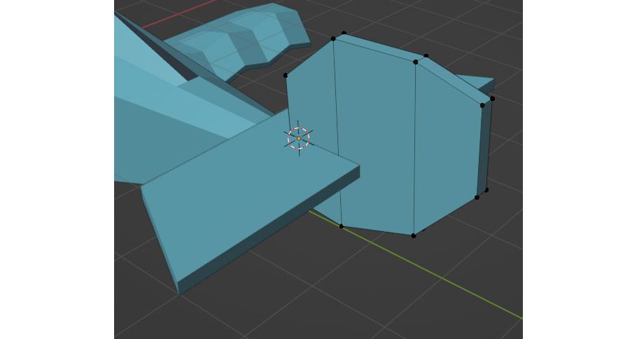
After adding a cube, I entered into Edit Mode once again and used S to scale it into the correct shape. In Vertex Select mode, I selected the outer vertices and moved them outward along the X Axis to form the angled shape of the vertical stabilizer.
For the rudder of the airplane I used a similar technique, but this time I also added two loops using Ctrl/Cmd – R, allowing me to create a more rounded shape.
Remember to keep applying the material and colors to each new object you add!
At this stage, here’s how the whole model is looking. We’re 80% of the way there with the basic shapes – now all we need is smaller details!
Now comes the fun part. In this section, I’m going to be adding all medium and small details to the airplane.
I’ll go over some of the larger parts and introduce you to a couple more tools, but after that I’ll challenge you to finish the aircraft on your own – by that point, you should have all the tools necessary to complete the job!
Before we get into the final steps, let’s talk a little bit about the design aspect of low poly modeling, and modeling in general.
For all kinds of modeling (and art in general), details are key to the final look. In realistic projects, adding small details is key to creating realism – even if they’re not modeled completely accurately, having tiny details present is better than not modeling them at all!
Surprisingly, that applies to low-poly style work as well. Obviously, low-poly models are never going to be realistic – but the more small details you add to your model, the more complete and well-rounded it looks in the end.
In stylized modeling, it’s also important to give your models character; and in low-poly style, usually the goal is to give models that “cute” look. The polygonal, simplified shapes already do this to some extent, but often we also change the size of certain details to give it a child-like appearance – for example, wings are shorter and thicker than in real life, wheels are larger, and the plane as a whole is shortened and a bit more rounded.
Let’s get back to modeling! Here, I’m starting by refining the shape of the engine cover object.
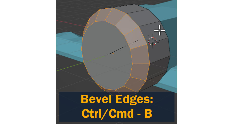
To start out, select the edge loop surrounding the front face by pressing 2 to enter Edge Select mode, and Alt/Option – Left Clicking the circle of edges. This will automatically select every edge along the loop of edges, cutting down on the time it takes to select things!
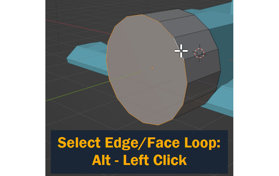
Next, with those edges selected, press Ctrl/Cmd – B to Bevel them, creating a more rounded profile on the engine cover. Move the mouse to change the amount of bevel, and Left Click to confirm when you’re done.
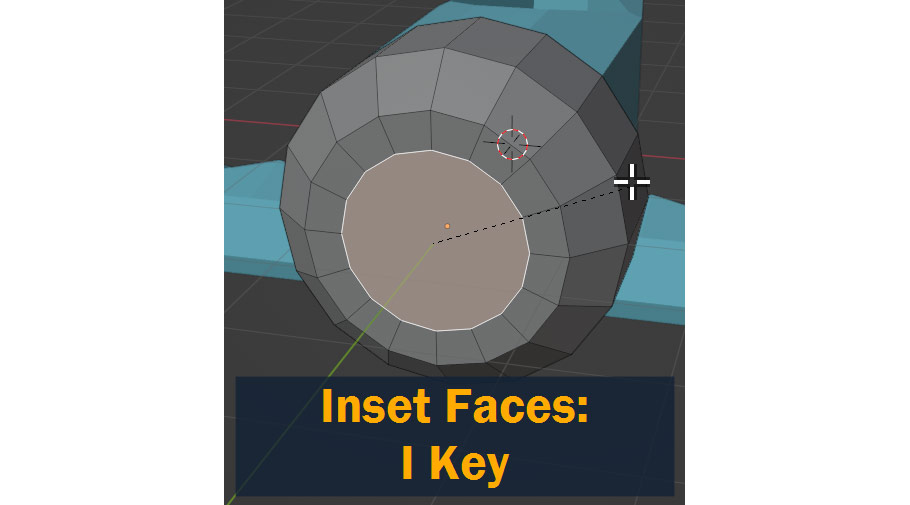
We also need to create a hole in the front of the engine cover for the propeller assembly to go through. First, let’s Inset the front face using the I key.
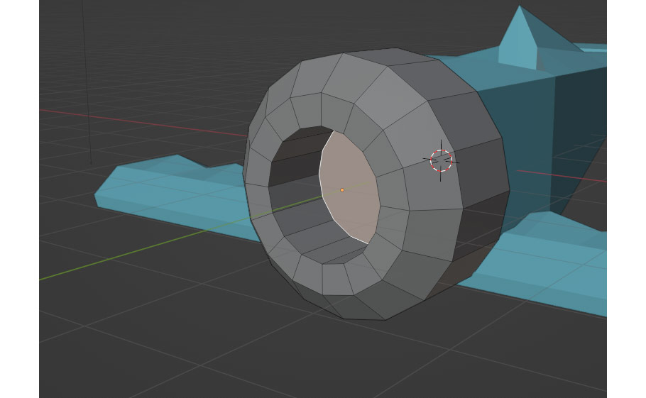
I then used E to extrude the new, smaller face inward as shown:
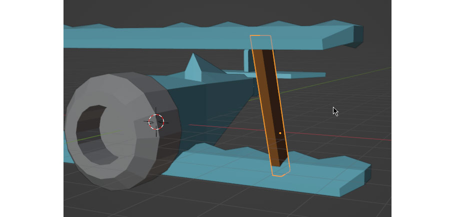
For this step, I started by creating a wing-strut on the biplane. I started with a Cube, scaled it to be tall and thin, and used G to move the top vertices forwards giving it an angled shape.
But now how do we mirror this to the other side of the model? For this, we need to move the object’s Origin to the center of the scene – when we Symmetrize using Shift – M, Blender flips the model around the Origin point, so if the origin point isn’t centered, the mirroring action won’t work as expected.
In Blender, the Origin point for a selected object is shown as an orange dot.
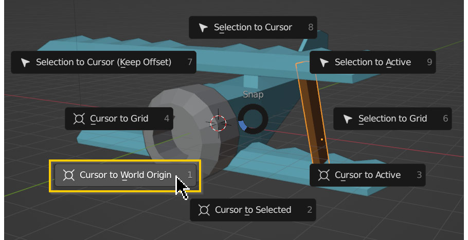
So, before we mirror the strut model, we need to move its origin to the center of the scene – and for this we’ll be using the 3D Cursor again.
Start by moving the 3D cursor to the center of the scene by pressing Shift – S and selecting Cursor to World Origin.
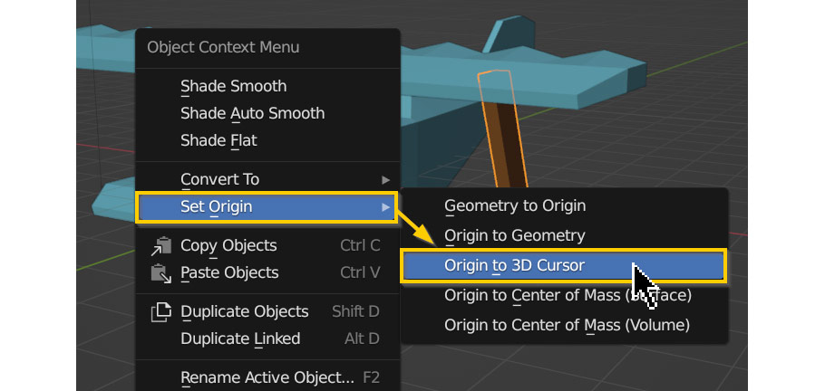
Now, we can Right Click our strut object and choose Set Origin > Origin to 3D Cursor.
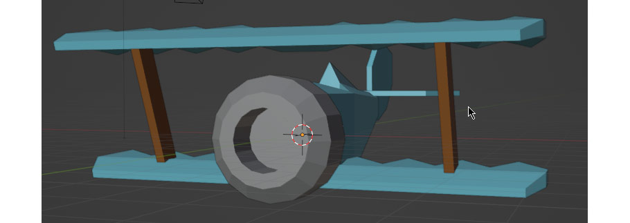
Now, when we mirror the strut in edit mode using Shift – M, it will appear on the other side of the model as expected!
This is where I leave you to finish the details on your own!
But don’t worry – before you go off on your own, I’ll leave you with a list of all the tools we’ve learned so far, as well as a few new ones that might come in handy. If you get stuck on a particular part, refer back to this list for ideas!
And of course, for many of these you can also lock to an axis using X, Y, or Z, or exclude an axis using Shift – X, Y, or Z.
Now, let’s go over a few additional features that might come in handy while finishing up the model!
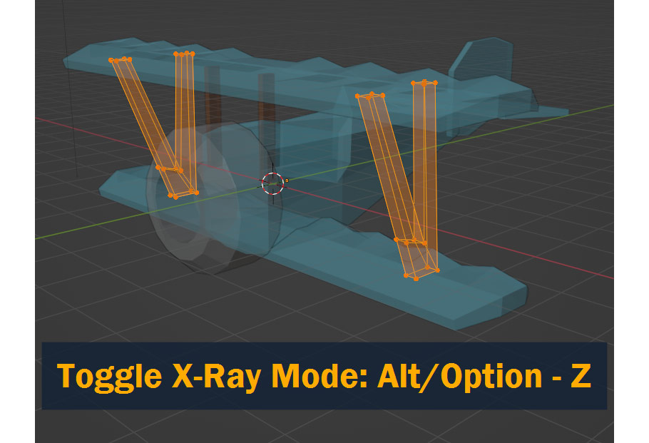
To see objects behind other objects, toggle X-Ray Mode by pressing Alt/Option – Z.
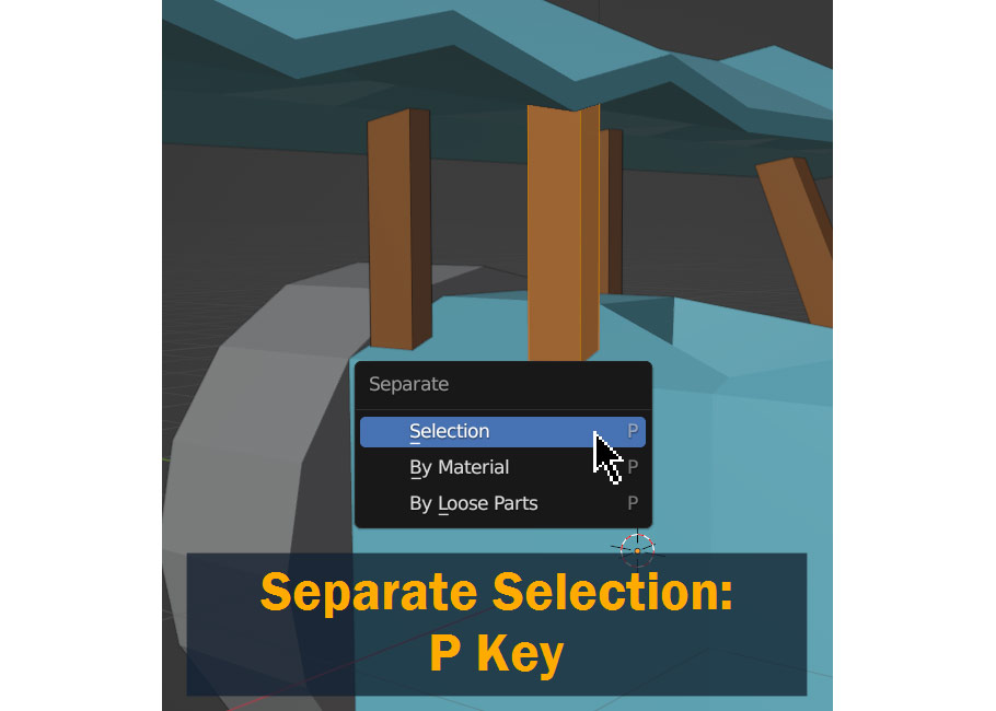
To separate a selection into its own new object, press P and choose Selection.
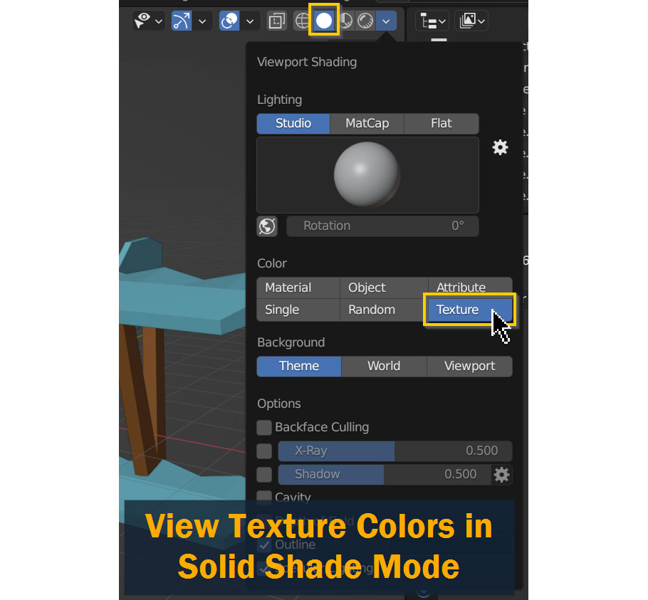
To view the texture on your object in the default viewport shading mode as I’ve been doing in previous screenshots, open Viewport Shading in the top right corner of the viewport and set Color to Texture as shown:
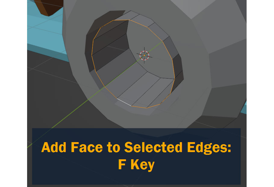
To create a new face from selected edges, press F:
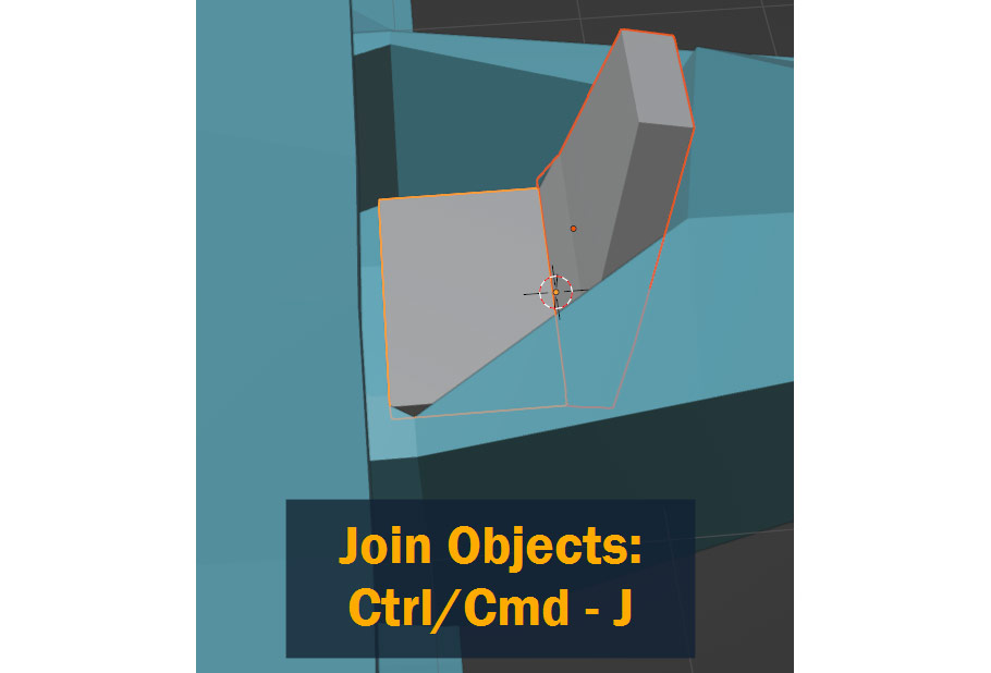
Finally, to Join two or more objects together into one, press Ctrl/Cmd – J.
After refining and detailing the airplane model using the tools I’ve mentioned, here’s the final result:
As you can see, I added more struts, landing gear, a propeller, circular markings, a seat, and a windshield. For your own plane, feel free to take inspiration from what I’ve done here – or customize it and make it your own!
Whatever you decide to do, I hope you were able to take away something useful from this tutorial. Whether you’re trying to break into the game industry, creating a game of your own, or just learning 3D for fun, you’re in for an exciting ride!
Best of luck on this and future projects – and thanks for reading!
Hello! I’m a self-taught 3D modeler and texture artist with experience on a variety of projects, ranging from planet creation to game props, vehicles, and environments. Although I’ve tried out a bit of everything, my main software is Blender. I’m a big fan of sci-fi and fantasy shows and books like The Expanse and Lord of the Rings, so most of my personal work has a fantasy or sci-fi theme – but I also love to experiment and try new things!


Add a comment