 Cars
Cars
 Trucks
 Buses
Buses
 Motorcycles
 Military
 Electronics
 Guns
Guns
 Buildings
 Aircraft
 Furniture
 Characters
 Animals
 Spacecraft
 Food
Food
 Ships
Ships
More
Hello everybody! Today we begin series of lessons dedicated to car modeling. And we will design together not just some Honda or Citroen, but a true Group B World Rally champion. So then, meet with Lancia Rally 037!

But first a small lyrical digression: Lancia Rally 037 was built purely for the rally championship and it was designed exclusively for the rally group B. And, as everybody knows, the car managed the task excellently: it won the manufacturers’ world championship in the 1983 season. It was the last rear-wheel drive car, which won the WRC.
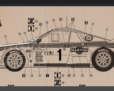
In this series of lessons I’m going to work with Autodesk 3ds Max, but you can use any 3D computer graphics software, since any of them has approximately the same pipeline. Also we will need some blueprints. As our blueprints we will use this picture:

For this we create a “Plane” in your units with parameters 762×1382, because the original image resolution is 762×1382.

Now we open “Material Editor” and set the material with already loaded texture.

Then convert to “editable poly”.

To convert the image in an appropriate orthogonal view we need to split up our mesh. Tick off “Preserve UVs” and mark the necessary dividing lines on the plane. The check mark near “Preserve UVs” allows to move loops without affecting the texture lying on the plane.


I’ve marked the necessary loops with red color, so it would be more convenient for us to put together our blueprints.
Next, we split our image into component parts and we place the appropriate planes to each other in order to see at the right side only that part of the texture, which corresponds to the right-side view.

Pay your attention that the loops, marked with red, must coincide and make one single line.

Now move your planes a little farther away from the prospective place of modeling. The planes should be moves only on the perpendicular to themselves.

Then, we create a layer called “blueprints”, put there our blueprints and perform the following operations:


Now we can proceed to modeling.
I warn you that blueprints, which are available online, are prepared by people, who sometimes are not closely related to the production. So don’t trust them unquestioningly. Look sometimes at live photos; blueprints give just a general idea of ??car features.
To begin with, we need to draw the car body as a whole and then cut wheel arches and all the details it in. Such approach allows us to draw the body as neat as possible immediately eliminating all irregularities, if they occur. Since the front part is the most complicated part of any car, let’s start with it.
We make a box, convert it to editable poly and then begin to adjust it to the blueprint.
Don’t forget to create a new layer for it to be separate from our blueprints. Let’s name it “Car”.


Our aim is to adjust mesh lines as much as possible to the lines of the blueprint, but at the same time we should avoid that the mesh become too dense. Few polygons are going to look good, and then, when cutting the wheel arches, it will play a dirty trick on us. Further will be fewer words but more pictures. I will primarily describe methods with words and then I will just refer to them, pointing what element I’ve made with the help of this or that method.
Let’s leave three polygons from our cube; we don’t need the rest of them.

Adjust the lateral convexities of the front fender as from the view from above.

I add extra loops using the button “connect”.

Now we have to adjust our loops, so that from the right-side view their curvature corresponds the curvature of the hood.

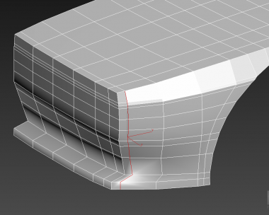
Pay your attention to the fact that Lancia 037 has two edges between the hood and the front fender.

It isn’t visible very well on all photos, but you can clearly see it on this one:

This must be taken into account immediately.
Adjust the upper edge as from the view from above.

The lower one as from the right-side view.

If we switch to the front view, we can see that the edges don’t coincide with this view. This is the effect that I’ve mentioned above when the blueprints don’t correspond to the original. In this case you should look at the photos and trust your instincts.

We continue to adjust loops; now we need to add some longitudinal loops.


Now in the frontal plane.

Please, also take into account the fact that cars never have straight lines. Even the Lamborghini Countach :-) Everything is a little bit curved. And you also should avoid absolutely straight lines.
Before we proceed to the detailed elaboration of our model, we will draw first a blank model of the whole car. When we have a blank model it is easier to see how we should draw that or this element. Think about the work of the sculptor: before making the facial features of a statue, he is making a half-finished statue. And we will do the same.
Draw a few extra loops on the fender in order to make it easier the drawing of the blank model.

Now let’s define a deepening on the bumper, but don’t be in a hurry, we will do everything step-by-step.

Choose these three points.

Switch to the frontal plane to define the main features of the bumper in the front.

Now it’s high time we looked at the photo. Unfortunately, blueprints usually don’t give a clear view of the body’s curves according to the height of the fender. Therefore you’ll have to evaluate the curve by eye and draw it on the model.
I got something like this.

Don’t worry about the fact that it didn’t turn smoothly and authentically. Now it’s just a “block out”. And we need it only in order to define the general shape. We’ll adjust it more accurately when the wheel arches are ready, because after this layout geometry will definitely change. But too curvy mesh is also bad.
The blank of the front part is ready. It’s practically the most difficult part of our blank model. And not only because it is the most important part, but also because we had to start with something.
Now we should pass from the front part of the body to the rest of it. Our Lancia 037 is a sports car and the front fender isn’t going straightly to the door: there is a ledge for an air inlet. It has a complicated shape so it will be better to make this element right away in the blank.
Choose these edges.

Switch to the “Select and Move” mode, and with the help of “click & drag” extrude these edges.

Try to do so that the polygons were regular. As far as possible, of course.
Now choose the “ring” edge.

Make a “connect”, select features so that the new loop conformed to the blueprint.

“Click & drag” to connect the new loop.


But in order to make a joint, you need to select the appropriate edges and press the button “bridge”.

Now we’ll easily join all parts to each other.
I‘m going to settle the gray material on the mesh, as it’s comfortable to work with (this is a very subjective feeling).
“Click & drag” to create a template for a windscreen.


At once adjust new polygons as on the blueprints.


Let’s complete the joint and that will be enough for today. Again, “Click & drag” and “bridge”.


Do not leave new polygons in such a way, level them at once.

Well, for today our lesson is over. Don’t be in a hurry to continue, for the beginners we’ve already done a great job today. Remember that everything should be gradual.
Have a nice rendering!
)
this modeling pogram is good
Can it be applied in blender. I think yes .what u think?
very nice
i want to use this to design something here
Nice 3d car modeling tutorial. thanks a lot
Great car 3D modeling tutorial. Easily understandable. Its really good. I hope u continue to do good work.