

 Cars
Cars
 Trucks
 Buses
Buses
 Motorcycles
 Military
 Electronics
 Guns
Guns
 Buildings
 Aircraft
 Furniture
 Characters
 Animals
 Spacecraft
 Food
Food
 Ships
Ships
More
Merry Christmas everybody! After a short break we are again with you! During our absence we were reflecting on how to make this world a better place and the first thing we would like to begin with making the world better is presenting you a BFG. Noooo, not this BFG:

Our BFG means a Big Free Gift! It’s Christmas, after all!
To be more exact, it would be a Big Free Tutorial. After we will finish our series of lessons on the creation of Lancia Rally 3D model, we are going to gather all pieces and parts in one big and handy tutorial! And, as it comes from the name, it will be available to all of you.
By the way, we haven’t mentioned BFG without a reason. On the 10th of December the world celebrated the 20th anniversary of the release of the legendary Doom! We would like to congratulate everybody who has fond and happy memories connected with this game!

And now, after all these sweets and cakes, it’s high time to get back to the lesson.
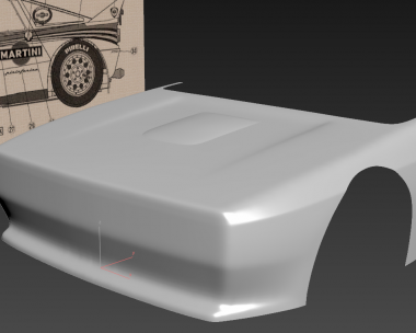
Now we will continue our work on car 3d modelling with the front part of the body. We have performed some curves approximately, but some moments require high precision. For example, headlights. They are perfectly round, and the best way to make them perfectly even and smooth is to duplicate the primitive shape. Let’s place here a cylinder and duplicate its cap on the front part with the help of the tool “cut”.


As you can see, cylinder’s position in conformity with the longitudinal axis doesn’t matter for us. Next, we select our model and using “cut” we just click on the tops of the cylinder. Be sure to switch on “snaps”.


You should get here such a ring.
Do not hurry up to remove the original cylinder. Mark the place for the second headlight in the same way.

Let’s draw at once the other key elements of the body. Here we are going to cheat a little. Select these edges and connect them.


Activate constraints to edges.

Drag these edges to level them with this point (don’t forget that “snaps” should be switched on!).

And connect this vertex.


With the help of “cut” connect these vertices.


Now, we remove these polygons, we no longer need them. In addition, it will facilitate the process of topology optimization.


Using “cut” we create one more line.

And we remove these polygons.

Our blank is ready for optimization. Since not all elements are ready, we are not going to fix all problem places now. Nevertheless, while adding new elements, we will have to optimize geometry from time to time as we can’t let topology drift. If you leave a lot of errors, it will be very difficult to fix them later. Therefore, we will fix only some problem places now to the extent that we could work comfortable without any troubles.
I’m not going to describe our every step now; you just look and do the same.


The further topology optimization rests on the creation of new elements. That’s exactly what we’re gonna do now.


So, here comes the time for tricks.

And here we need to apply “flow connect”. But, if we apply it now, the new edges will bend not in the way we want. I would say it would be quite unacceptable.

The new edges will continue the curve of these edges. But if we split them for a while, “flow connect” won’t take them into account.


Now need to re-weld vertices.
And even here there are some tricks. The matter is that “weld” tool is a little bit unscrupulous – sometimes, there is a risk of collapse of the vertices you would like to leave. Here you have another trick: select these two edges.

Don’t worry; there are two edges indeed, because, as you should remember, we have spited them earlier. Then select edge loop.

And remove extra edges from the selected ones.

Apply “weld”.

If the command welds edges not in the way you need, you can regulate weld threshold.
Let’s continue our work.

We need to move this edge loop a little bit down, so that it would be in the middle of the holes in the bumper. Don’t forget to activate “constraint edge”.

We also need to set bumper curve. When we were drawing it in the very beginning we let go a lot of inexactitudes, and now it’s high time to fix them. Drag this group forward.


After these geometry corrections we need to straighten the other nearby points,

We apply “flow connect” on the selected edge ring.


Here we need to separate our mesh. This will facilitate our work.


And we continue.


Everything resulted right, but in these places we have some curvature. This should be corrected manually.


In the area number one you can see an excessive prominence. We will get the same in the second area when we separate the mesh there as well. Nevertheless, we don’t need to fix it straight away; we will do it when it comes the right time for this.


Move these edge loops (edge constraint enabled) to outline the hole.


These points should be leveled in one vertical line. With their help we outline the right edge of the hole.


Let’s continue.


Yes, we resulted with a lot of edges. But that is the deal: with less number of edges the model will have a flat shape.


It will be better to detach this piece of the surface, because we are likely to need it later.


If you apply TurboSmooth, you will be able to see some dents in these places. They have appeared because our vertices which are situated there lay unevenly. We will have to level these folds by eye.


Now let’s check our model again. No visible folds are supposed.
Then, we repeat the trick with “flow connect” and we separate the piece from the mesh.


And don’t forget to weld everything in one single piece after this.
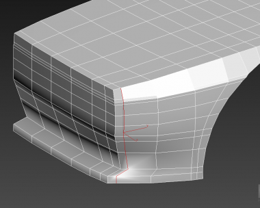
Select these polygons.

Create an inset of approximately 4mm.

Remove these two polygons.


Select the edges, which were emerged after we created the inset, and the edges, which lie inside the hood, and remove them.


Please, pay your attention that in some places may appear such ‘tails’ that must be removed with the help of “target weld”.

Now level these edges here with the symmetry plane.


This thin line of polygons must be removed as well.


Perhaps, it’s enough for today. Next time we will proceed. Stay with us!
Enjoy, comment, post…
have a nice render and a happy New Year!


)
Add a comment