
 자동차
자동차
 트럭
트럭
 버스
버스
 모터사이클
모터사이클
 군용 차량
군용 차량
 전자 기기
전자 기기
 무기
무기
 건축물
건축물
 항공기
항공기
 가구
가구
 캐릭터
캐릭터
 동물
동물
 우주선
우주선
 음식
음식
 선박
선박
보기
For a lot of 3D art, realism, accuracy, and consistency are key. In visual effects, props, set pieces, and vehicles need to look exactly like their real-life counterparts, and in modern day films and even games, the bar for realism is set very high!
So what’s the solution? Often, it’s photos. When modeling real-life objects, 3D artists will almost always work from photographs – sometimes photos are just used as reference, but as we’ll see in this tutorial, a lot of the time 3D artists will directly “trace” 2D photographs or drawings while modeling for extra accuracy.
In this article I’ll cover all the basic tools and steps to setting up a reference image, and go through the whole process of creating a model from scratch!
But before we begin – do we even need to model at all? Can’t we just feed the photo into some AI program and make it do the hard work? Well, at the time of writing this article, sadly the answer is no. There is technically software that can convert photos into models using AI, but at the moment it’s a long way from being able to generate any usable models. If you google it, it might seem like there are some good options – but when you dig a little deeper, none of the services that advertise great results actually use AI to generate the models. They’re either using limited procedural modeling algorithms, or even just hiring actual human 3D modelers to do the work and pretending it’s AI!
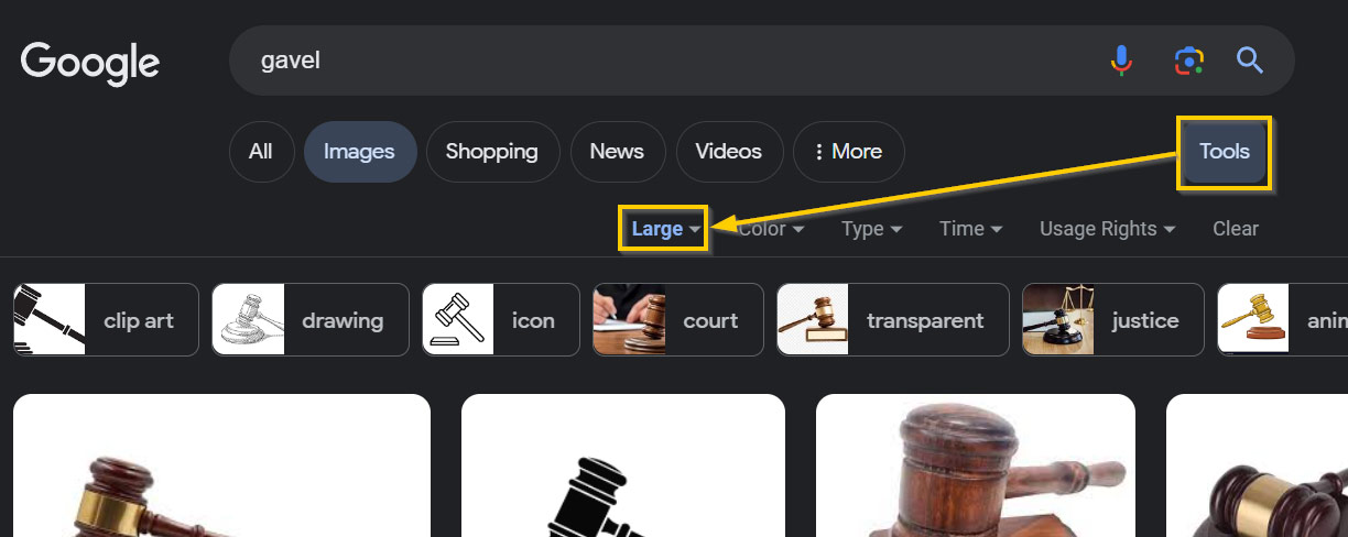
Before we get started in Blender, let’s talk a little bit about finding good reference images! For this tutorial, I decided to create a gavel, like you might see in an American courthouse or in government meetings.
So, where do we find reference for this? Well, the best place to look is usually good old Google images.
When looking for reference photos, there are a few specific things to look out for – not all photos are created equal. Here are a few things to keep in mind when looking for good photos of your subject:
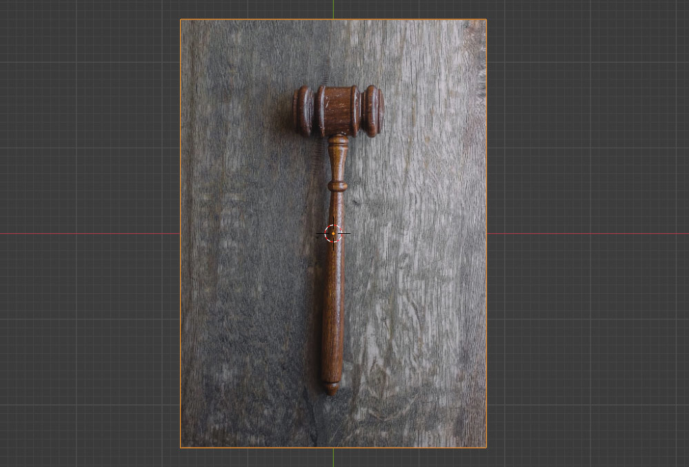
This is the JPG image I ended up going with. This is a good example of a reference photo – neutral lighting and colors, adequate resolution, and a fairly perspective-free, top-down angle!
For more complex models, it can be useful to find reference images from side view and front view as well – but for this, that’s not really needed.
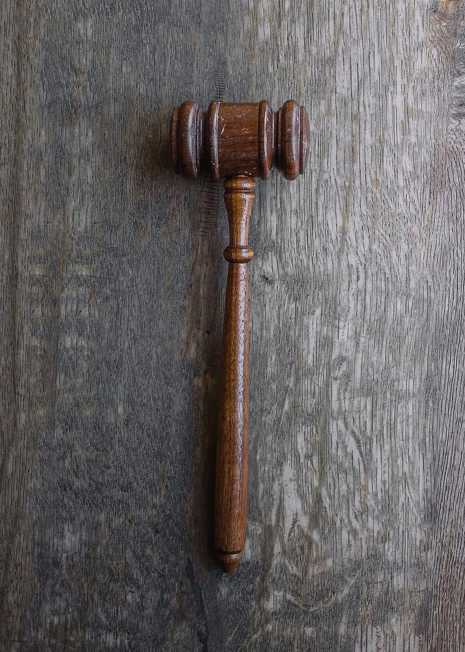
Although license doesn’t usually matter for reference images (since they aren’t going to appear in the final product), for the purpose of this tutorial I went with a copyright-free photo – if you’re following along, you can download it for free here.
(Thanks to Wesley Tingey for taking the photo and making it free to use!)
Now that we’ve got our reference image, let’s open Blender and get it set up for modeling!
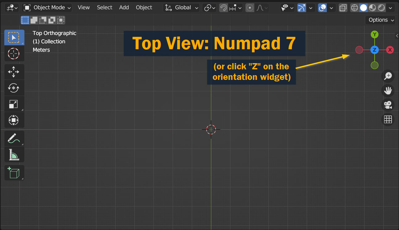
To start with, let’s align our viewport with the view that we’ll most often use for modeling – in this case, let’s go with a top view. To do this, press 7 on your numberpad, or click the blue Z marker on the orientation widget in the top right of the viewport.
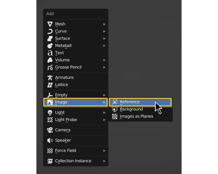
Now let’s add the photo! Press Shift – A to open the Add menu, go to Image and select Reference as shown.
In the Blender file browser window that pops up, navigate to the location of your reference image on your computer, select it, and click Load Reference Image. By default, it will match the rotation of the viewport – so if you’re in top view, it should appear flat on the world grid!
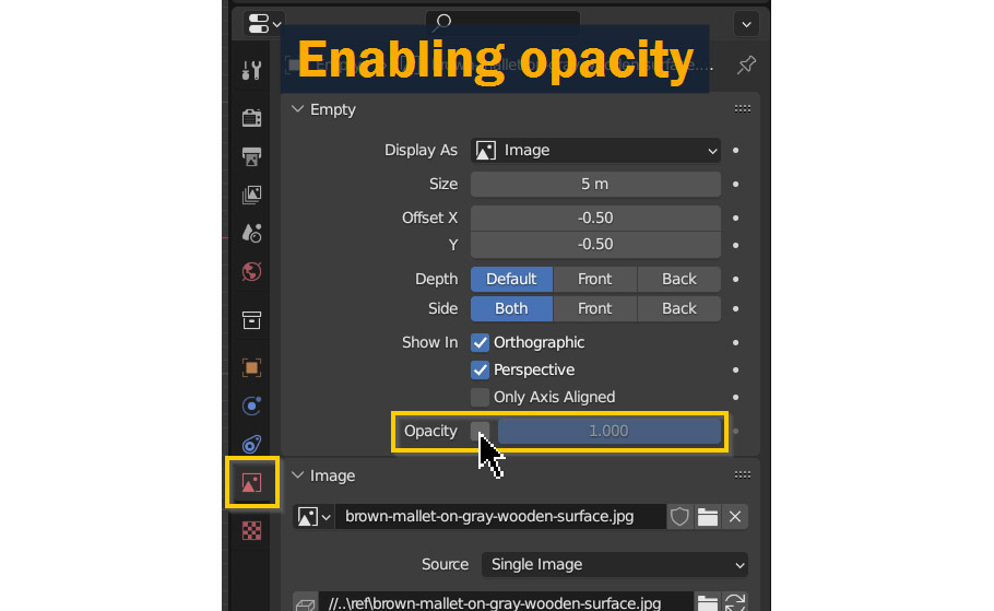
Now, since this is a real-life photograph, the subject won’t be 100% aligned and centered. To some degree this is something we have to accept while modeling, but we can improve the situation a bit manually – to start with, go to the Properties Panel, and in the tab with the Image Icon, enable Opacity as shown. This will allow the world grid to show through the image, making it easier to center and align the photo!
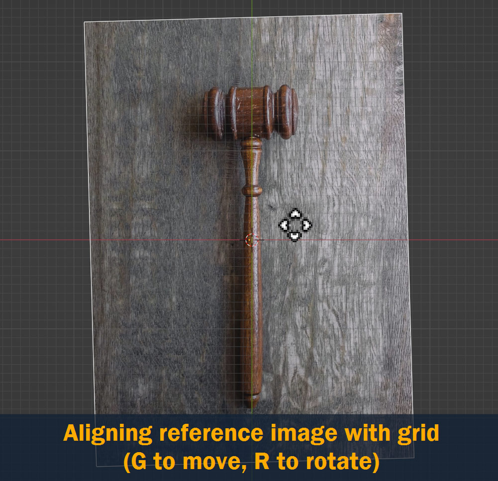
Now, using the G key to move and the R key to rotate, center the image as best you can along the green Y Axis. You probably won’t be able to get it 100% perfect – with many photos, perspective and distortion can make even perfectly straight objects look bent or uneven. I’ll talk about a couple methods to get around this later on.
With the reference image now set up, you’re ready to start modeling.
Let’s get into the modeling process! In this section, I’ll go over all the steps I took to create the final model, including all the methods I used to match the model with the reference photo. I’ll divide this section into steps to make it easier to follow!
Like any 3D modeling project, we’ll start by adding a primitive object to our scene to build from – let’s create a Cylinder, which will become the handle of our gavel.
Press Shift – A to open the Add menu, and select Mesh > Cylinder.
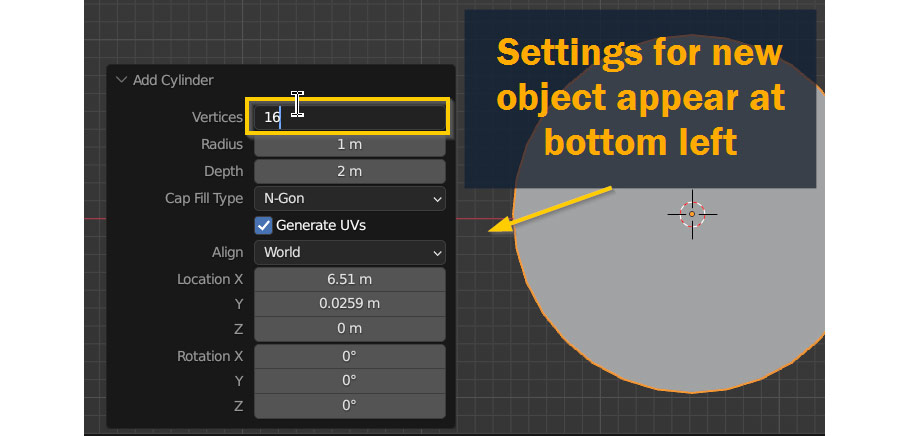
Since we’ll be adding resolution using Subdivision later on, let’s reduce the resolution on the base cylinder to begin with – open the Add Cylinder pop-up at the bottom left of the viewport, and change Vertices to 16 instead of 32. For a thin object like this, we don’t need that many vertices!
Next rotate your cylinder 90° along the X Axis by pressing R, X, typing 90, and then hitting Enter. After entering Edit Mode, this is what we’ve got so far:
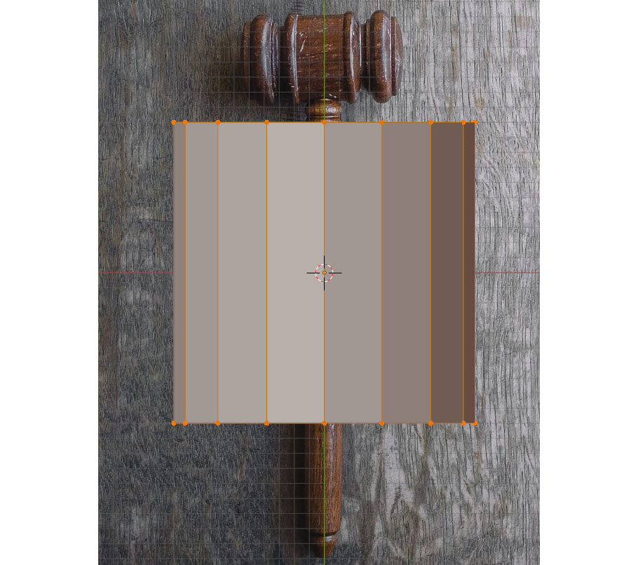
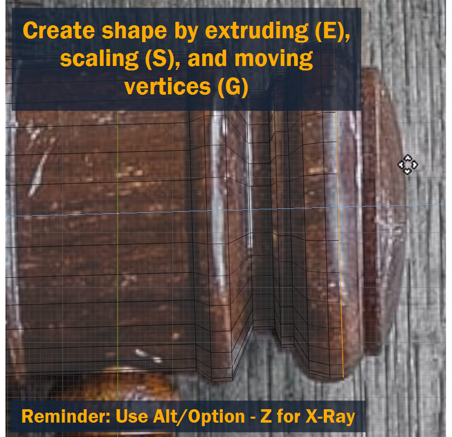
As you can see, at the moment the 3D model is covering up the reference image – this isn’t great, because we can’t see the photo we’re trying to follow! To fix this, turn on X-Ray mode by pressing Alt/Option – Z. Now we’ll be able to see the reference through the model, as shown:
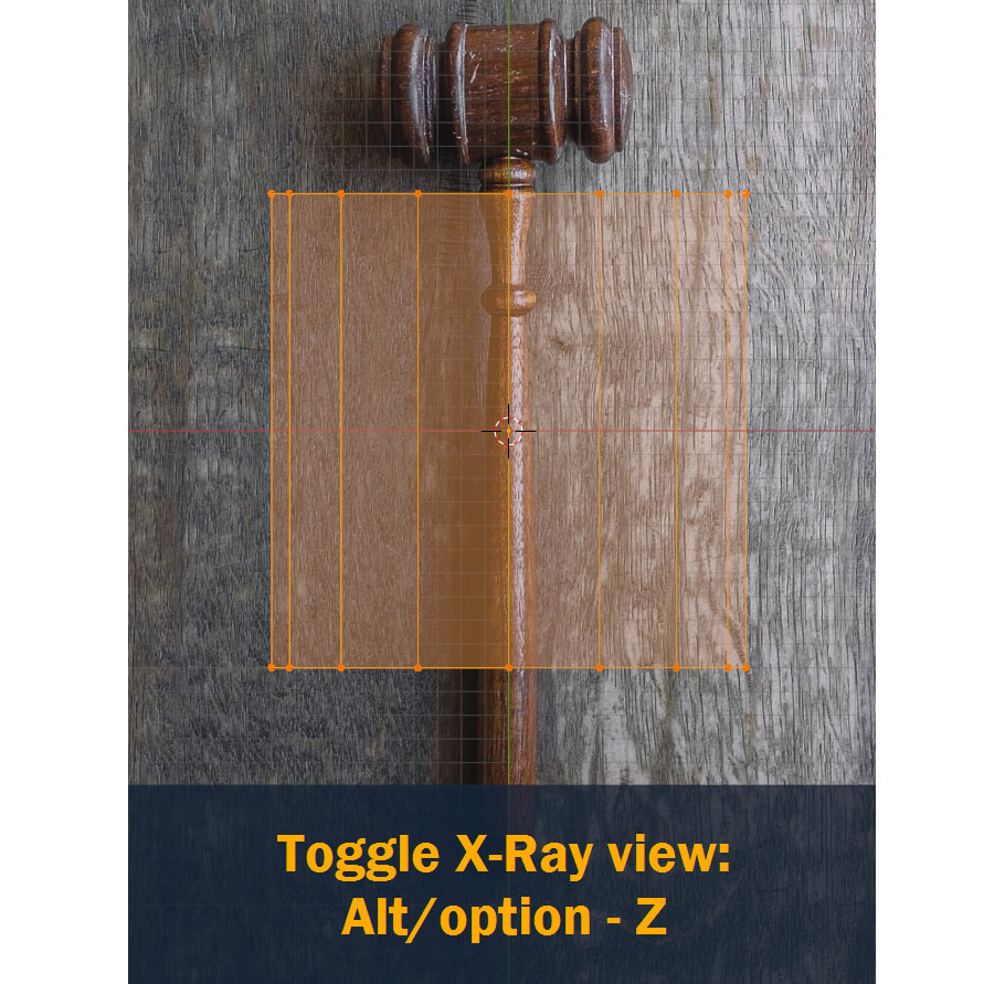
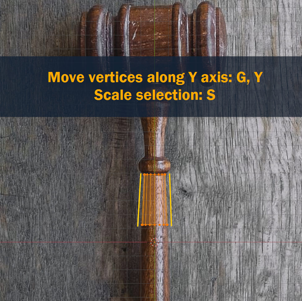
Now we can start forming the shape of our model. You can select rings of vertices on your model by Left Clicking and Dragging, and scale them down to match the width of gavel in the image using S.
To position the vertices along the length of the handle, move them along the Y axis by pressing G, and then Y to lock movement to the Y Axis.
Obviously, you’ll need more than one basic cylinder to create the handle – so to add new sections, select the face/vertices on the end of your model and press E to Extrude the face, and scale it to match the geometry using S.
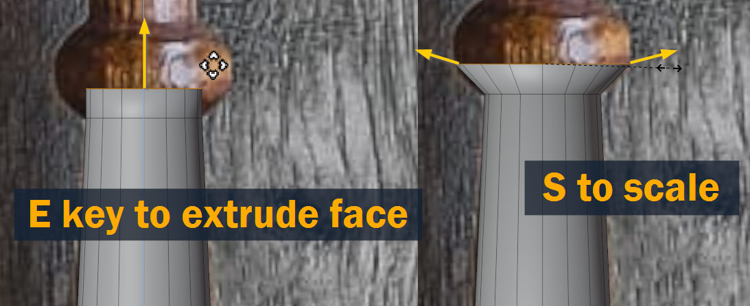
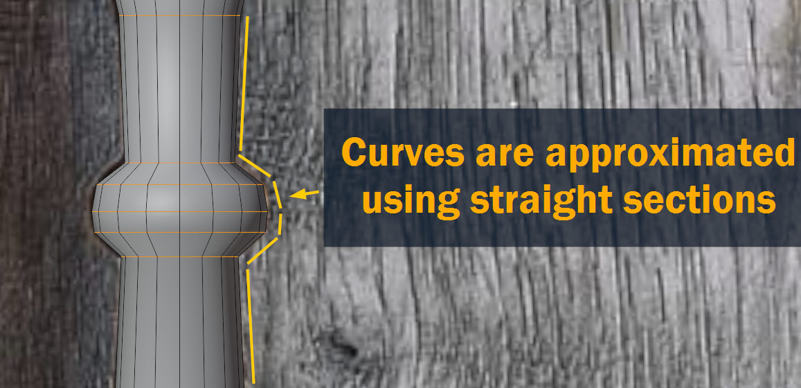
The goal at this stage isn’t to exactly reproduce the curves on the model – instead, we’re using a minimum amount of vertices to approximate the curve of the real-life object. Later, we’ll apply a Subdivision modifier which will turn this low-poly model into a smooth, high-poly surface!
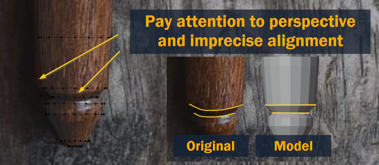
While modeling, watch out for any perspective, distortion, or incorrect angles in your reference. No photo is perfect – so when you’re tracing over a reference photo in this way, sometimes you’ll have to use your own reasoning and knowledge of the model to decide how to model the object.
For example, my reference photo shows this groove at the bottom of the gavel as curved, but I know that this is caused by perspective – so on my model, I make those rings straight.
After extruding, moving, and scaling the vertices all along the length of the handle, this is what we end up with:
For this part, start by switching back to Object Mode.
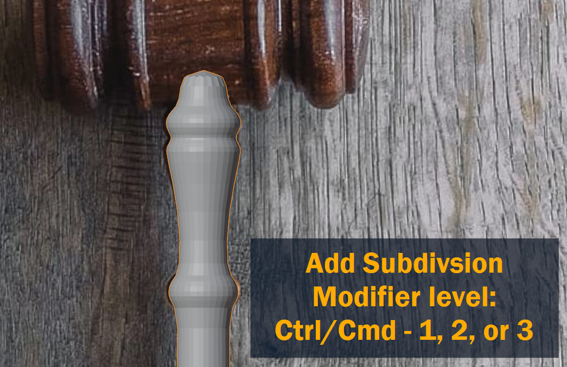
Like I mentioned above, we’re now going to smooth out the model using a Subdivision modifier!
You can do this by going to Properties Panel > Modifier Properties and adding a Subdivision modifier, but a quicker way to do this while in the viewport is to press Ctrl/Cmd – 1 or 2. This will automatically add a subdivision modifier set to the chosen value – 2 will add more faces, but 1 will be faster. Technically you can choose any number up to 6, but I don’t recommend going above 2 for this project – 2 is smooth enough!
You might notice that after subdividing, your model is too smooth – the rounded parts have been smoothed off, but so have all the hard edges that were supposed to stay hard! Luckily, this is easy to fix.
Back in Edit Mode, you can control how the model is smoothed by adding Holding Edges in places where you want transitions to be harder. To do this, press Ctrl/Cmd – R to activate the Loop Cut and Slide tool – hover over your model, and click to add a loop on a ring of faces – then, move the mouse to slide the loop towards other edges on your model to tighten up those areas. Click again or press Enter to confirm!
Lastly, to display your model as fully smooth, in Object Mode, Right Click your object and press Shade Smooth.
That’s the handle completed! Now, let’s start on the head section of the gavel.
Since the head is essentially a cylinder, just like with the handle we’re going to add a Cylinder object using Shift – A.
Since the head is larger than the handle, this time it’s probably a good idea to set Vertices to 32 instead of 16!
Here’s the cylinder after moving it into position using G, Y:

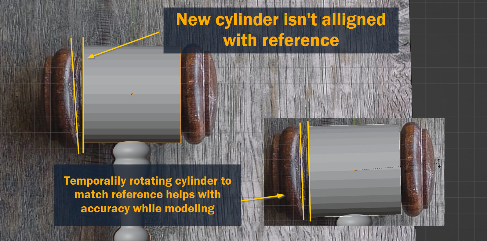
You might notice that after creating the cylinder, it isn’t quite aligned with the head of the gavel in the photo, likely because of perspective in the photo.
In the finished model we’ll want the head aligned properly, but for now it’s actually a good idea to temporarily rotate the cylinder object to match the reference – otherwise, tracing the curved shape will be impossible! So, rotate the cylinder to match the reference using R.
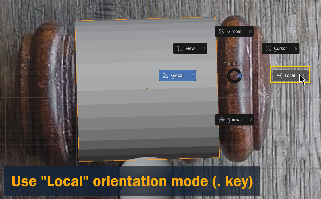
Once the cylinder is rotated, you’ll also need to switch to Local orientation mode – otherwise, your actions on the model won’t align with the slightly-rotated cylinder. To do this, press the Period key on your keyboard and select Local.
With the cylinder in place and orientation set to local, let’s get modeling again!
We can use the same tools as we did for the handle – although this time, since we’re in Local orientation mode, we’ll be moving things along the local Z Axis instead of the Global Y – so instead of pressing G, Y, we’ll be pressing G, Z.
As a reminder, the other tools we’ll be using are E to extrude faces and S to scale!
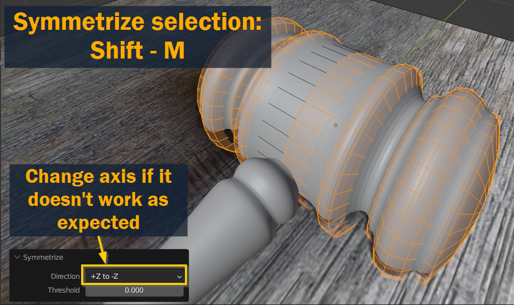
Once you’ve modeled one side of the head, you can mirror it to the other side using Shift – M. At first it won’t work properly, because you’ll need to change the Direction in the Symmetrize pop-up – depending on how you modeled it, you’ll either need to select +Z to -Z or -Z to +Z. Try them both if you’re unsure.
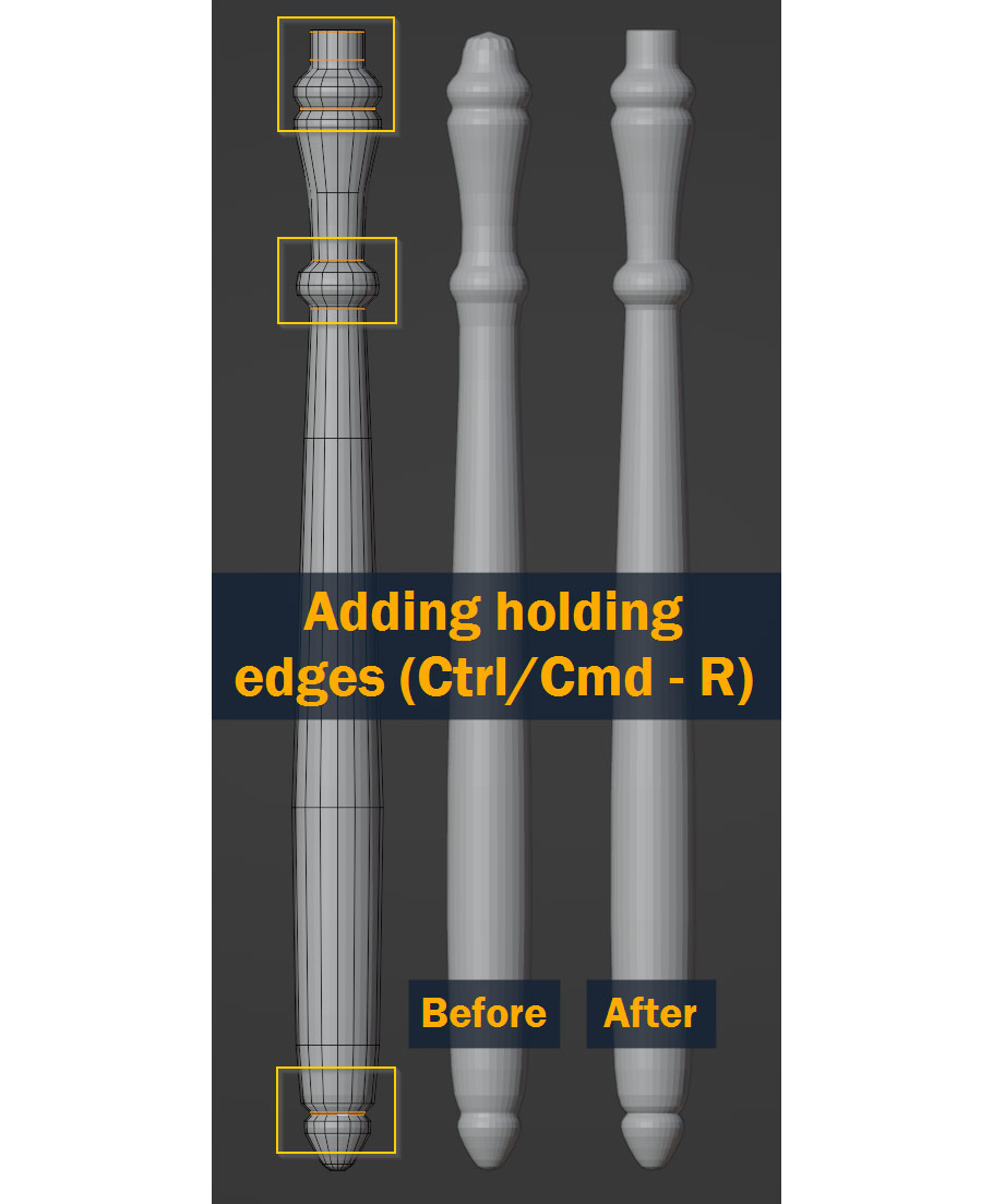
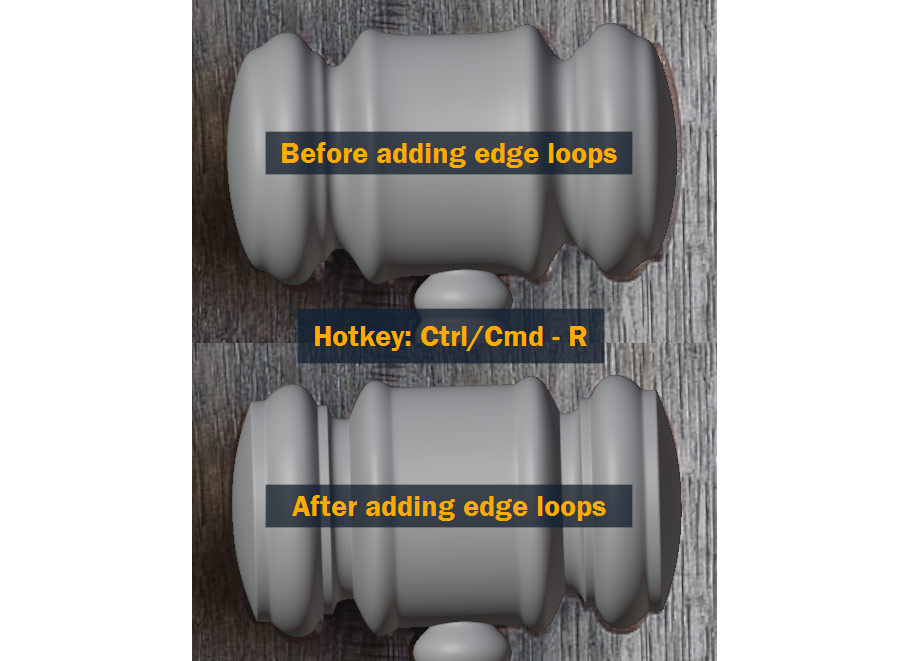
After adding subdivision to the head by once again pressing Ctrl/Cmd – 1 or 2 while in Object Mode, we’ll once again need to add Holding Edges using Ctrl/Cmd – R.
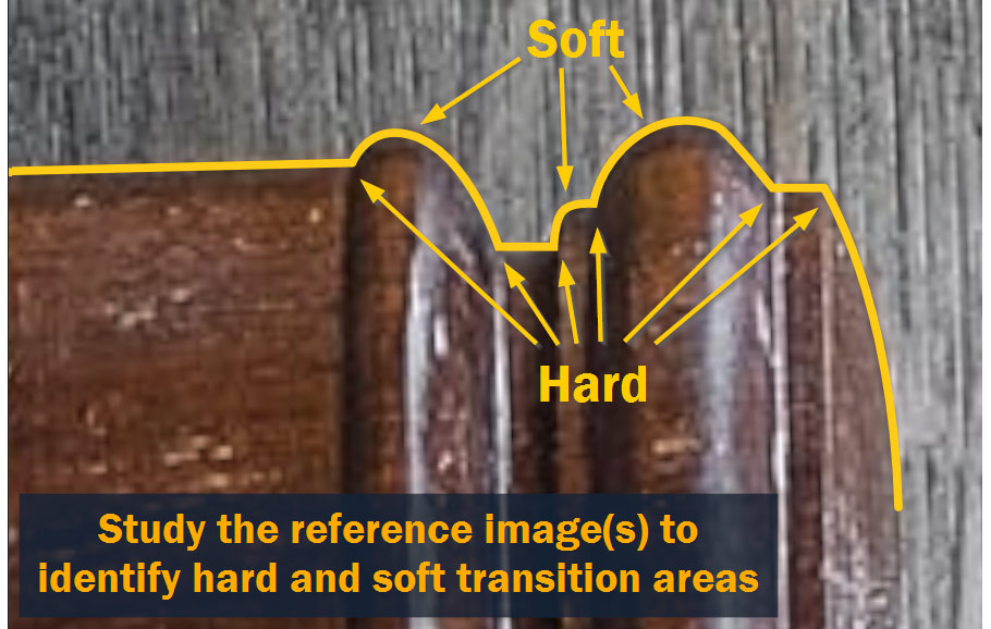
To figure out where to add them, study the reference – soft, curved transitions won’t need any edge loops added, but hard edges will need loops added on one or both sides of the original edge.
Here’s the model, before and after adding the holding edges:
Looking pretty good!
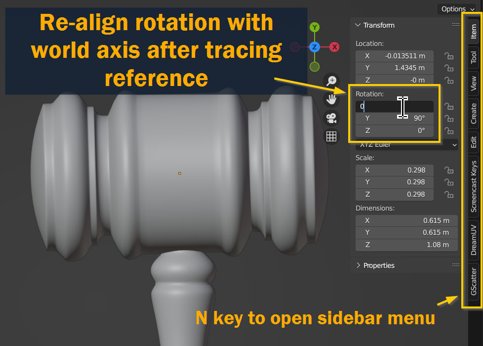
Once you’re done modeling, let’s straighten out the head object again to align with the world axes.
To do this, go to the Item tab of the Sidebar Menu. You may have to open the sidebar first using the N key.
To reset the rotation of the head object, look under Rotation; as a general rule, to re-align a slightly-rotated object with the world axes, you’ll want to round all the values to either 0°, 90°, or -90° – this way, movements along the world X, Y, and Z axes will align with the model.
So, that’s the head and handle complete, right? Well, almost – but since we’re going for realism and accuracy here, let’s add a hole for the handle to go into. Needless to say, in real life objects don’t just phase through each other!
For this step, we’re going to be using a Boolean modifier. This will let us use a small cylinder to cut a hole into the larger one.
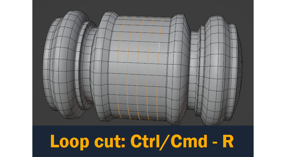
But first, we have to prepare the larger cylinder. When using Booleans, you always want to have an even surface to apply the cutter to – it’s best to avoid elongated, thin faces; ideally, you want the surface to be an even, square grid.
To get this on our gavel head, we can add some loop cuts across the cylinder using Ctrl/Cmd – R as shown:
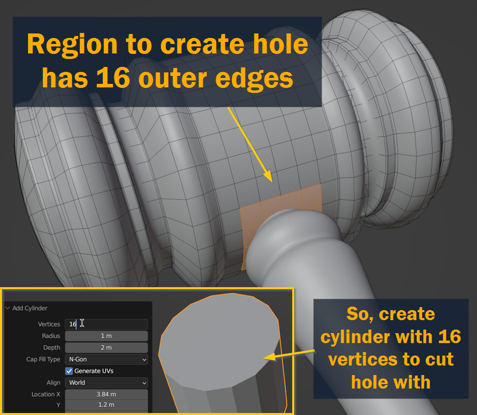
Now that we have an even surface to apply our boolean to, let’s define the area that we want the hole to be in.
We can see that the area which the handle connects to has 16 outer edges when selected – so for our hole cutter, we’ll want to add a cylinder with 16 vertices as shown!
To precisely align the new cutter cylinder with the location of the hole, select the faces in the hole region, press Shift – S, and select Cursor to Selected to move the 3D Cursor to the selected faces.
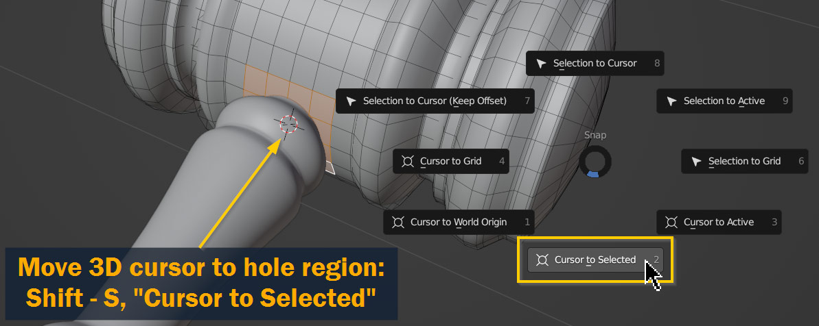
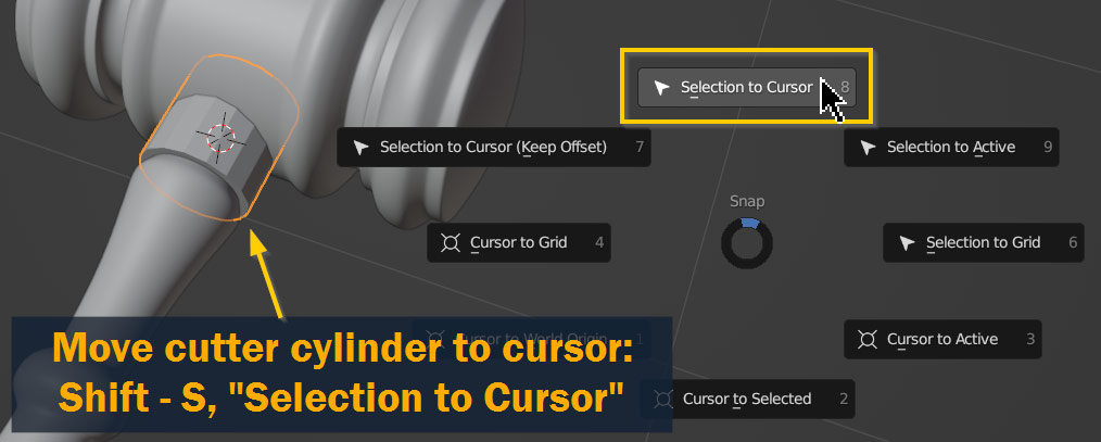
Now, with the cutter cylinder selected in Object Mode, press Shift – S again and select Selection to Cursor.
You’ll also need to rotate the cutter cylinder 90° along the X Axis to align it with the handle (shortcut: R, X).
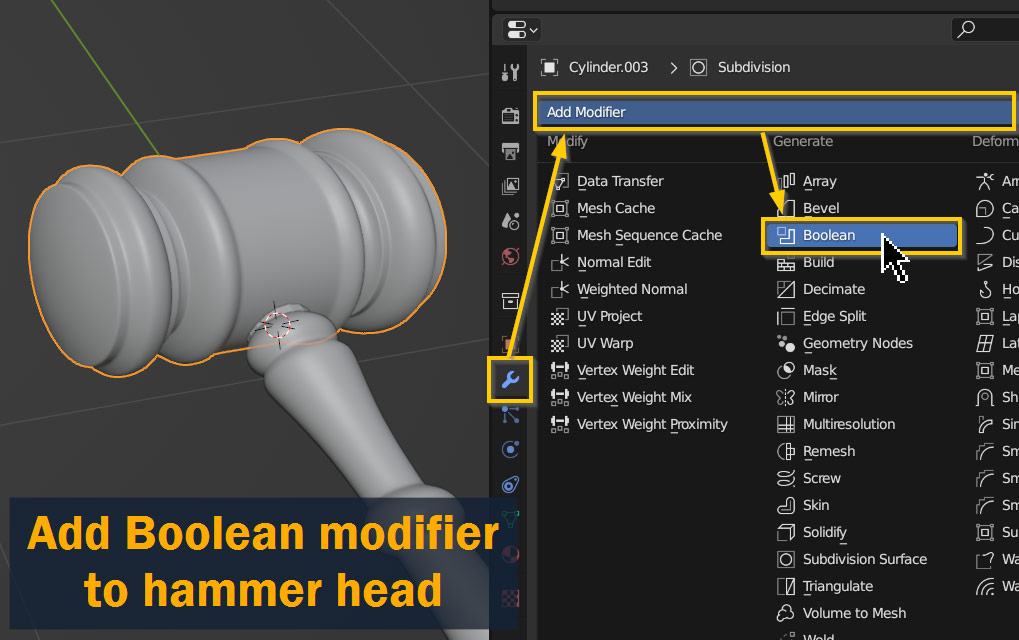
Now let’s add a Boolean modifier to the hammer head!
In object mode, select the object – now, go to the Properties Panel, and open the Modifier Properties tab (wrench icon). Press Add Modifier and choose Boolean from the dropdown.
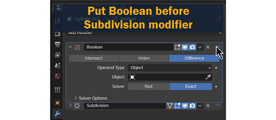
Before anything else, the Boolean modifier needs to go before the subdivision modifier in the modifier stack – so click on the grid of dots at the top right corner, and drag it upwards to the top.
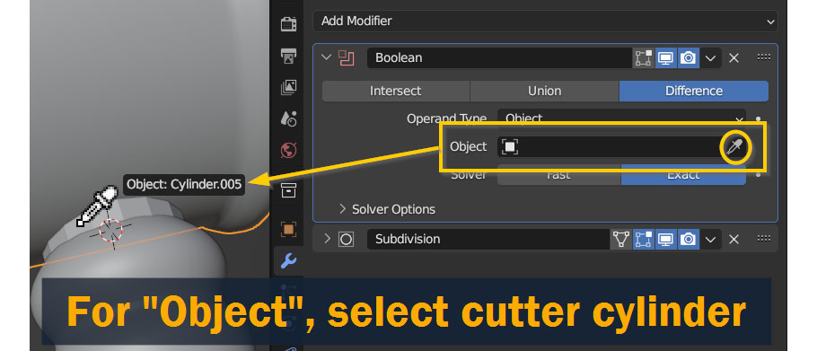
Now, for Object, click on the Eyedropper tool and select the cutter cylinder you added before. You’ll notice that as soon as you select the cutter, the area around the hole starts looking strange – but don’t worry, we’ll fix that in the next steps!
Before we fix the issues, Apply the modifier to the mesh by pressing the dropdown in the modifier title bar and pressing Apply as shown.

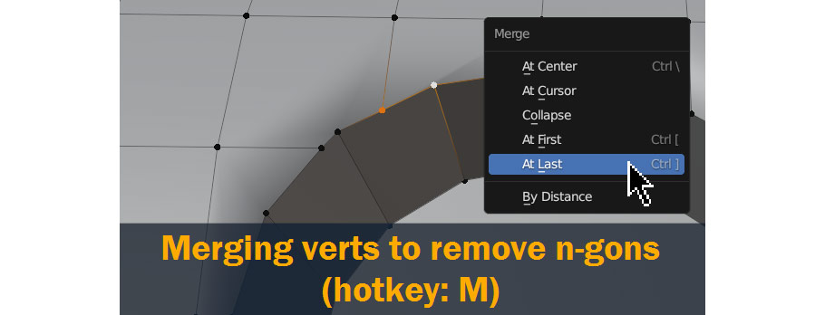
The issues you’re seeing show up are caused by n-gons in your model, which are faces with more than 4 sides – these don’t subdivide very well! To clean things up, we’ll need to get rid of all of these – and for this, we’ll use the Merge and Join tools. In the end, we want all the faces in this area to be quads, which are faces with four sides.
To start cleaning things up, you can merge one vertex into another by selecting them both, pressing M, and selecting At Last – this will merge the first selected vertex to the location of the last.
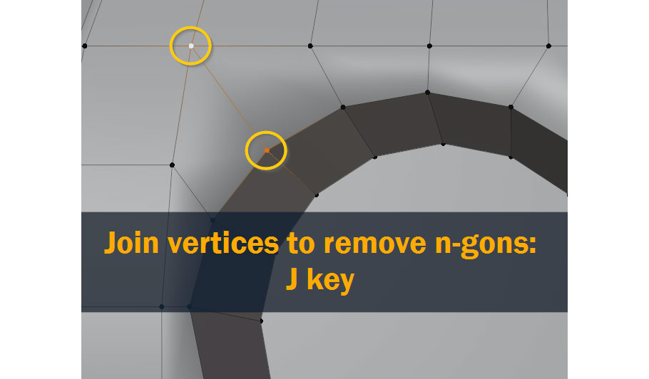
You can also Join vertices together with edges by pressing J on your keyboard!
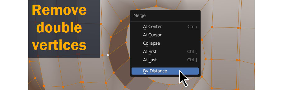
It’s also always a good idea to Merge by Distance after using a boolean – sometimes, booleans create overlapping vertices and this will remove them. So press M again, and select By Distance!
After adjusting the topology, I also used Ctrl/Cmd – R to add some supporting edge loops to sharpen up the edges, just like we did on the head and handle of the gavel.
Here’s a before and after comparison:
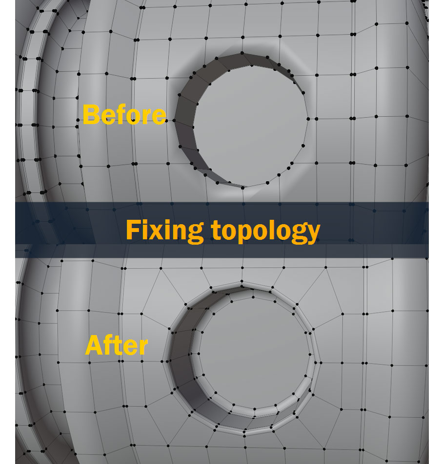
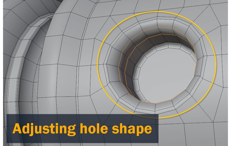
Always check the reference before and after doing something like this – in my case, after looking at the reference image, I ended up scaling the inner faces inward a bit and adding a couple more edge loops on the inside as shown:
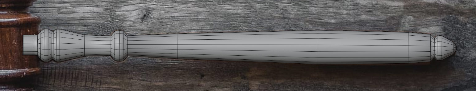
With that, the model is complete!
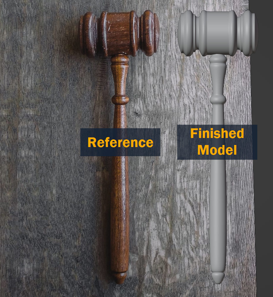
Here again is the final result, like I showed at the beginning:
That concludes this tutorial! I hope you learned something useful from this – although this was a fairly simple project as far as 3D modeling goes, the methods for working with reference images I introduced here will be useful on any project where you’re working from a photo.
Feel free to let me know your thoughts in the comments below – tips, suggestions, and discussion are all welcome!
Thanks for reading, and best of luck on all your future projects!
Hello! I’m a self-taught 3D modeler and texture artist with experience on a variety of projects, ranging from planet creation to game props, vehicles, and environments. Although I’ve tried out a bit of everything, my main software is Blender. I’m a big fan of sci-fi and fantasy shows and books like The Expanse and Lord of the Rings, so most of my personal work has a fantasy or sci-fi theme – but I also love to experiment and try new things!


Add a comment